- English
- Čeština
- Italiano
- Deutsch
- Polski
- Français
- Home
- Troubleshooting [進行中の翻訳]
- プリンタートラブルシューティング
- Selftest failed (XL multi-tool)
Selftest failed (XL multi-tool)
- プリント品質のトラブルシューティング
- QR Error codes [進行中の翻訳]
- プリンタートラブルシューティング
- A64 Overheat #10207 (SL1/SL1S)
- 周囲温度のチェック(MK3/MK3S)
- Ambient temperature too cold #10703 (SL1/SL1S)
- Ambient temperature too high #10702 (SL1/SL1S)
- An unexpected error has occurred #10701 (SL1)
- Another action is already running #10506 (SL1/SL1S)
- BBF Allocation Failed #17531 (XL)
- BBFの割当に失敗しました #26531 (MK4S) #13531 (MK4) #21531 (MK3.9) #23531 (MK3.5)
- BBF Initialization failed #17532 (XL)
- BBFの初期化に失敗しました #26532 (MK4S) #13532 (MK4) #21532 (MK3.9) #23532 (MK3.5)
- ヒートベッド最高温度エラー #26205 (MK4S) #13205 (MK4) #21205 (MK3.9) #23205 (MK3.5)
- ヒートベッド最低温度エラー #26207 (MK4S) #13207 (MK4) #21207 (MK3.9) #23207 (MK3.5)
- ベッドプリヒートエラー #26201 (MK4S) #13201 (MK4) #21201 (MK3.9) #23201 (MK3.5)
- ヒートベッドの熱暴走 #26203 (MK4S) #13203 (MK4) #21203 (MK3.9) #23203 (MK3.5)
- 飛んだフューズ (MINI)
- Blown Fuse (MK2S/MK2.5/MK2.5S)
- 飛んだヒューズ (MK3/MK3S/MK3S+)
- 飛んだヒューズ (MK4/S, MK3.9/S)
- Blue Screen of Death (BSOD)
- Boost board problem #10320 (SL1S)
- Bricked printer (SL1/SL1S)
- Calibration project is invalid #10543 (SL1/SL1S)
- Can't copy project #10704 (SL1/SL1S)
- Cannot get update channel #10514 (SL1)
- Cannot read project #10539 (SL1/SL1S)
- Cannot remove project #10545 (SL1/SL1S)
- ホットエンドの詰まり (MK4)
- ホットエンドの詰まり (XL)
- ノズル/ホットエンドの詰まり (MINI/MINI+)
- ノズル/ホットエンドの詰まり (MK3.5/S, MK3S+, MK2.5S)
- 接続認証の失敗
- Connect Registration Failed #12401 (MINI)
- 接続認証の失敗 #17401 (XL)
- Connect Registration Failed #21401 (MK3.9)
- Connect Registration Failed #23401 (MK3.5)
- Connect Registration Failed #26401 (MK4S) #13401 (MK4)
- Directory not empty #10546 (SL1/SL1S)
- Disconnected UV LED panel #10321 (SL1/SL1S)
- Display test failed #10120 (SL1/SL1S)
- Dwarfボードエラー #17502 (XL)
- Dwarfボードエラー #17503 (XL)
- EEPROM I2C Receive Busy #17316 (XL)
- EEPROM I2C 受信ビジー #26316 (MK4S) #13316 (MK4) #21316 (MK3.9) #23316 (MK3.5)
- Emergency stop #12510 (MINI)
- Emergency stop #17510 (XL)
- 緊急停止 #26510 (MK4S) #13510 (MK4) #21510 (MK3.9) #23510 (MK3.5)
- ESP error #17504 (XL)
- ESP error #17505 (XL)
- ESP error #17506 (XL)
- ESPエラー #26504 (MK4S) #13504 (MK4) #21504 (MK3.9) #23504 (MK3.5)
- ESPエラー #26505 (MK4S) #13505 (MK4) #21505 (MK3.9) #23505 (MK3.5)
- ESPエラー #26506 (MK4S) #13506 (MK4) #21506 (MK3.9) #23506 (MK3.5)
- ESP not connected #17533 (XL)
- Expect overheating #10714 (SL1/SL1S)
- External SPI flash W25X20CL/xFLASH が反応しない - エラー
- エクストルーダーのブロブ
- EXTRUDER ERROR #17536 (XL)
- Extruder Maxtemp error #17206 (XL)
- Extruder Mintemp error #17208 (XL)
- エクストルーダーのノイズ
- エクストルーダー プリヒートエラー #17202 (XL)
- Extruder temp not matching #17210 (XL)
- エクストルーダーの熱暴走 #17204 (XL)
- プリント途中でエクストルーダーの押し出しが止まる現象(ヒートクリープ)
- ファクトリーリセット (MINI)
- ファクトリーリセット (MK2S/MK2.5S/MK3S)
- 工場出荷時の状態へのリセット (MK4/S, MK3.9/S, MK3.5/S, XL)
- Factory Reset (MMU)
- Factory reset (MMU2S pre firmware 1.0.6)
- Factory reset (SL1/SL1S)
- Failed to read the configuration file #10505 (SL1)
- Zキャリブレーションの失敗 (MK3S/MK2.5S)
- Fan failure #10106 (SL1/SL1S)
- Fan warning #10713 (SL1/SL1S)
- フィラメントのアンロード失敗(MINI/MINI+)
- フィラメントがロードされていかない
- フィラメントがロードされない (MK4/S, MK3.9/S)
- フィラメントがロードされていかない (XL)
- フィラメントセンサー (MK4/S, MK3.9/S, XL)
- File already exists! #10520 (SL1)
- File not found #10518 (SL1/SL1S)
- File system error #12613 (MINI/MINI+)
- ファイルシステムエラー #26613 (MK4S) #13613 (MK4) #21613 (MK3.9) #23613 (MK3.5)
- FINDA setup and troubleshooting
- FINDA: Filament Stuck #04102 (MMU)
- Firmware in the internal flash corrupted! #12608 (MINI)
- Firmware missing #17612 (XL)
- Firmware Update Required #26701 (MK4S) #13701 (MK4) #21701 (MK3.9) #23701 (MK3.5)
- ファームウェアのアップデート時の問題 (MK2.5S/MK3S+/MMU2S/MMU3)
- First layer does not stick (SL1/SL1S)
- Flash erase error #12605 (MINI/MINI+)
- Flash erase error #17605 (XL)
- フラッシュ消去エラー #26605 (MK4S) #13605 (MK4) #21605 (MK3.9) #23605 (MK3.5)
- FW in internal flash corrupted #17608 (XL)
- 内蔵メモリ内のFWが破損しています #26608 (MK4S) #13608 (MK4) #21608 (MK3.9) #23608 (MK3.5)
- Hash verification failed #12607 (MINI/MINI+)
- Hash verification failed #17607 (XL)
- ハッシュの検証に失敗 #26607 (MK4S) #13607 (MK4) #21607 (MK3.9) #23607 (MK3.5)
- ヒートベッドが正常に加熱されない
- ヒートベッドポートの過電流 #26309 (MK4S) #13309 (MK4) #21309 (MK3.9) #23309 (MK3.5)
- Heatbed temp not matching #17209 (XL)
- Heatbreak Maxtemp error #17212 (XL)
- ヒートブレイク最高温度エラー #26212 (MK4S) #13212 (MK4) #21212 (MK3.9)
- Heatbreak Mintemp error #17211 (XL)
- ヒートブレイク最低温度エラー #26211 (MK4S) #13211 (MK4) #21211 (MK3.9)
- Homing Error #12301 (MINI)
- Homing error X #12304 (MINI/MINI+)
- Homing error X #17304 (XL)
- X軸ホーミングエラー #26304 (MK4S) #13304 (MK4) #21304 (MK3.9) #23304 (MK3.5)
- Homing error Y #12305 (MINI/MINI+)
- Homing error Y #17305 (XL)
- Y軸ホーミングエラー #26305 (MK4S) #13305 (MK4) #21305 (MK3.9) #23305 (MK3.5)
- Zホーミングエラー #17301 (XL)
- Homing Error Z #23301 (MK3.5)
- Z軸ホーミングエラー #26301 (MK4S) #13301 (MK4) #21301 (MK3.9)
- ホットエンドファンが回転しない
- Hotend Heater Overcurrent #17322
- Hotend maxtemp error #23206 (MK3.5)
- Hotend mintemp error #23208 (MK3.5)
- ホットエンド最低温度エラー #26208 (MK4S) #13208 (MK4) #21208 (MK3.9)
- Hotend preheat error #23202 (MK3.5)
- ホットエンドプリヒートエラー #26202 (MK4S) #13202 (MK4) #21202 (MK3.9)
- Hotend temp not matching #13210 (MK3.9/MK4)
- Hotend temp not matching #23210 (MK3.5)
- Hotend thermal runaway #23204 (MK3.5)
- ホットエンドの熱暴走 #26204 (MK4S) #13204 (MK4) #21204 (MK3.9)
- I2C Receive failed #17315 (XL)
- I2C受信の失敗 #13315 #26315 (MK4S)(MK4) #21315 (MK3.9) #23315 (MK3.5)
- I2C Receive Timeout #17317 (XL)
- I2C受信のタイムアウト #26317 (MK4S) #13317 (MK4) #21317 (MK3.9) #23317 (MK3.5)
- I2C Receive undefined #17318 (XL)
- I2C受信の未定義 #26318 (MK4S) #13318 (MK4) #21318 (MK3.9) #23318 (MK3.5)
- I2C Send Busy #17312 (XL)
- I2C 送信ビジー #26312 (MK4S) #13312 (MK4) #21312 (MK3.9) #23312 (MK3.5)
- I2C Send Failed #17311 (XL)
- I2C送信の失敗 #26311 (MK4S) #13311(MK4) #21311 (MK3.9) #23311 (MK3.5)
- I2C Send Timeout #17313 (XL)
- I2C送信のタイムアウト #26313 (MK4S) #13313(MK4) #21313 (MK3.9) #23313 (MK3.5)
- I2C Send Undefined #17314 (XL)
- I2C送信の未定義 #26314 (MK4S) #13314 (MK4) #21314 (MK3.9) #23314 (MK3.5)
- Imposter! Fake signature #17606 (XL)
- Incorrect printer model #10705 (SL1/SL1S)
- Internal memory full #10516 (SL1/SL1S)
- Invalid API key #10405 (SL1/SL1S)
- Invalid FW size on USB #12603 (MINI/MINI+)
- USBのFWサイズが無効 #26603 (MK4S) #13603 (MK4) #21603 (MK3.9) #23603 (MK3.5)
- Invalid FW size on USB flash drive #17603 (XL)
- IR filament sensor calibration (MMU3, MMU2S)
- IRフィラメントセンサーのトラブルシューティング(MINI/MINI+)
- IRフィラメントセンサーのトラブルシューティング(MK2.5S, MK3S)
- LCDスクリーンが機能しない
- LED Memory Error #17529 (XL)
- LEDメモリーエラー #26529 (MK4S) #13529 (MK4) #21529 (MK3.9) #23529 (MK3.5)
- Live Z adjust not saving
- Load to extruder failed #04108 (MMU)
- Loadcell Bad Configuration #17527 (XL)
- ロードセルのキャリブレーション不良 #26527 (MK4S) #13527 (MK4) #21527 (MK3.9)
- Loadcell measure failed #17526 (XL)
- ロードセル測定の失敗 #26526 (MK4S) #13526 (MK4) #21526 (MK3.9)
- Loadcell not calibrated #17523 (XL)
- ロードセル未キャリブレーション #26523 (MK4S) #13523 (MK4) #21523 (MK3.9)
- Loadcell tare error #17524 (XL)
- Loadcell Tare Error #26524 (MK4S) #13524 (MK4) #21524 (MK3.9)
- Loadcell tare failed #17525 (XL)
- ロードセル基準値の設定失敗 #26525 (MK4S) #13525 (MK4) #21525 (MK3.9)
- Loadcell timeout #17528 (XL)
- ロードセルのタイムアウト #26528 (MK4S) #13528 (MK4) #21528 (MK3.9)
- Loadcell troubleshooting
- Logging data over serial line (MMU2S)
- Loud noises from printer (SL1/SL1S)
- M.I.N.D.A./SuperPINDA センサーのテスト (MINI/MINI+)
- Marlin Request Timeout #17530 (XL)
- Marlin Request Timeout #26530 (MK4S) #13530 (MK4) #21530 (MK3.9) #23530 (MK3.5)
- Mask noavail warning #10709 (SL1/SL1S)
- ヒートベッドの温度エラー/Maxtemp error bed #12205 (MINI)
- ホットエンドの温度エラー/Maxtemp error print head #12208 (MINI)
- MCU Maxtemp Error #17213 (XL)
- ヒートベッドの温度エラー/Mintemp error bed #12207 (MINI)
- ホットエンドの温度エラー/Mintemp error print head #12208 (MINI)
- Misaligned PINDA Sensor (MK2/S)
- Missing parts (SL1/SL1S)
- MK3Sがフィラメント交換を促し続ける
- MMU MCU Underpower #04307 (MMU)
- MMU Overcurrent #26310 (MK4S) #13310 (MK4) #21310 (MK3.9) #23310 (MK3.5)
- MMU2S idler unable to move freely
- MMU2S LEDs meaning
- MMU2S Selector not moving
- Modular bed error #17250 (XL)
- Modular bed error #17251 (XL)
- Modular bed error #17252 (XL)
- Modular bed error #17253 (XL)
- Modular bed error #17254 (XL)
- モジュラーベッド エラー #17255 (XL)
- Modular bed error #17256 (XL)
- Modular bed error #17257 (XL)
- Modular bed error #17302 (XL)
- Modular bed error #17303 (XL)
- Modular Bed Error #17319 (XL)
- Modular Bed Error #17320 (XL)
- Modular bed error #17501 (XL)
- Multimeter usage
- No file on USB #12604 (MINI/MINI+)
- No file to reprint #10508 (SL1)
- No FW in internal flash #12612 (MINI/MINI+)
- 内蔵フラッシュ内にFWが存在しない #26612 (MK4S) #13612 (MK4) #21612 (MK3.9) #23612 (MK3.5)
- USBにファームウェアがありません #26604 (MK4S) #13604 (MK4) #21604 (MK3.9) #23604 (MK3.5)
- No FW on USB flash drive #17604 (XL)
- Not connected to network #10402 (SL1/SL1S)
- Not enough layers #10540 (SL1/SL1S)
- Not enough resin #10706 (SL1/SL1S)
- Nozzle Cleaning Failed (MK4, MK3.9)
- ノズルクリーニングの失敗 (XL)
- ノズルがヒートベッドに衝突する
- Nozzle Heater Overcurrent #23308 (MK3.5)
- ノズルヒーターへの過電流 #26308 (MK4S) #13308 (MK4) #21308 (MK3.9)
- Object cropped warning #10710 (SL1/SL1S)
- Opening project failed #10504 (SL1/SL1S)
- Out of memory #17507 (XL)
- メモリー切れ #26507 (MK4S) #13507 (MK4) #21507 (MK3.9) #23507 (MK3.5)
- M.I.N.D.A./SuperPINDA センサーのテスト (MINI/MINI+)
- Parameters out of range #10707 (SL1/SL1S)
- ピンが未到達 #17107 (XL)
- PNG Buffer Full #17508 (XL)
- PNGバッファのメモリ不足 #26508 (MK4S) #13508 (MK4) #21508 (MK3.9) #23508 (MK3.5)
- ベッドのプリヒートエラー #12201 (MINI)
- ホットエンドのプリヒートエラー/Preheat error print head #12202 (MINI)
- Preload failed #10503 (SL1/SL1S)
- Print examples missing #10523 (SL1/SL1S)
- プリントファンが回転していません
- プリンタの電源が入らない、または電源が切れたままになる
- Project analysis failed #10542 (SL1/SL1S)
- Project is corrupted #10541 (SL1/SL1S)
- PrusaLinkのトラブルシューティング
- Puppy error #17511 (XL)
- Puppy error #17512 (XL)
- パピーエラー #17513 (XL)
- パピーエラー #17514 (XL)
- Puppy error #17515 (XL)
- Puppy error #17516 (XL)
- Puppy error #17517 (XL)
- Puppyボードエラー #17518 (XL)
- Puppy error #17519 (XL)
- Puppy error #17520 (XL)
- Puppy error #17521 (XL)
- Puppy error #17522 (XL)
- Remote API error #10407 (SL1/SL1S)
- Resin low #10712 (SL1/SL1S)
- Resin measuring failed #10124 (SL1/SL1S)
- Resin sensor error #10307 (SL1/SL1S)
- Resin too high #10109 (SL1/SL1S)
- Resin too low #10108 (SL1/SL1S)
- Sample G-codes
- Saving log file (SL1/SL1S)
- SDカードが読めません
- SDカード・USBメモリ
- Selftest failed (XL multi-tool)
- Selftest procedure checks
- First, belts!
- Fan test
- Y and X axes test
- Z alignment calibration
- Dock Position calibration
- Loadcell test
- Nozzle diameter confirmation
- Z axis test
- Nozzle heater test
- Filament sensor
- Tool offset calibration
- Bed heater test
- Phase stepping calibration
- セルフテストの失敗 (XL)
- Signature verification failed #12606 (MINI/MINI+)
- 署名の検証に失敗 #26606 (MK4S) #13606 (MK4) #21606 (MK3.9) #23606 (MK3.5)
- SL1 Tilt-mechanism error
- スパゲッティモンスター
- MINIを正確に調整する
- ステータスLEDについて (MK4/XL)
- Status LED explained (MMU3)
- フィラメントスタックの検出 #26101 (MK4S) #13101 (MK4) #21101 (MK3.9) #17108 (XL)
- Tangled filament
- Temp not matching heatbed #12209 (MINI/MINI+)
- Temp not matching print head #12210 (MINI/MINI+)
- Temperature out of range #10208 (SL1/SL1S)
- Thermal runaway(ヒートベッド) #12203 (MINI)
- Thermal runaway(プリントヘッド) #12204 (MINI)
- TMC driver shorted #04304 (MMU)
- TMC driver shorted #04314 (MMU)
- TMC driver shorted #04324 (MMU)
- ツールオフセットが不整合 #17104 (XL)
- ツールチェンジャーエラー #17101 (XL)
- Toolchanger problem (XL multi-tool)
- Tower check failed #10118 (SL1/SL1S)
- Unauthorized #10406 (SL1/SL1S)
- Under-extrusion (Nextruder printers)
- Unexpected error #10501 (SL1/SL1S)
- Unexpected MC error #10306 (SL1/SL1S)
- Unknown printer model #10323 (SL1/SL1S)
- Unsupported BBF version #12614 (MINI/MINI+)
- サポートされていないBBFバージョン #26614 (MK4S) #13614 (MK4) #21614 (MK3.9) #23614 (MK3.5)
- Unsupported Buddy FW #17611 (XL)
- Unsupported firmware BBF file #17614 (XL)
- Unsupported printer model #17610 (XL)
- Unsupported printer type #12610 (MINI/MINI+)
- サポートされていないプリンタタイプ #26610 (MK4S) #13610 (MK4) #21610 (MK3.9) #23610 (MK3.5)
- Unsupported printer version #12611 (MINI/MINI+)
- サポートされていないプリンタバージョン #26611 (MK4S) #13611 (MK4) #21611 (MK3.9) #23611 (MK3.5)
- USB Device Overcurrent #17307 (XL)
- USBデバイスの過電流 #26307 (MK4S) #13307 (MK4) #21307 (MK3.9) #23307 (MK3.5)
- USB drive not detected #10528 (SL1/SL1S)
- USB flash drive not connected #17602 (XL)
- USB flash error #17613 (XL)
- USB not connected #12602 (MINI/MINI+)
- USBメモリが接続されていません #26602 (MK4S) #13602 (MK4) #21602 (MK3.9) #23602 (MK3.5)
- USB Port Overcurrent #17306 (XL)
- USBポートの過電流 #26306 (MK4S) #13306 (MK4) #21306 (MK3.9) #23306 (MK3.5)
- UV LED temperature error #10209 (SL1/SL1S)
- UV led voltage error #10309 (SL1)
- プリント中の振動とノイズ (MK3S+/MK2.5S)
- Wrong printer model #10544 (SL1/SL1S)
- Wrong revision of motion controller #10301 (SL1)
- XY position invalid #17106 (XL)
- XY probe unstable #17105 (XL)
- プリントエラーメッセージ
On the Original Prusa XL, the selftest checks for issues in the assembly of the printer, its wiring, and the electronic components. It is the first part of the Calibration Wizard, which is prompted automatically when you turn on the printer for the first time or after a セルフテストの失敗 (XL). After the initial calibration is completed, the selftest can be initiated in LCD Menu - Control - Calibrations & Tests.
Selftest procedure checks
- Fan test
- Y axis test
- X axis test
- Z alignment calibration
- Dock position calibration
- Loadcell test
- Nozzle diameter confirmation
- Z axis test
- Nozzle heaters test
- Filament sensor calibration
- Tool offset calibration
- Bed heater test
- Phase stepping calibration
Progress and results of each step are displayed on the LCD screen. After the selftest, you can check the results at any time in the printer menu at LCD Menu -> Control -> Calibrations & Tests. If the step fails, it will show a red "x" near it.
First, belts!
The belts will affect most of the selftest procedures on your Original Prusa XL. Because of that, carefully read the prepared guide about ベルトの調整方法 (XL) in case you have any issues with your selftest related to the axes, dock position calibration, or tool offset calibration.
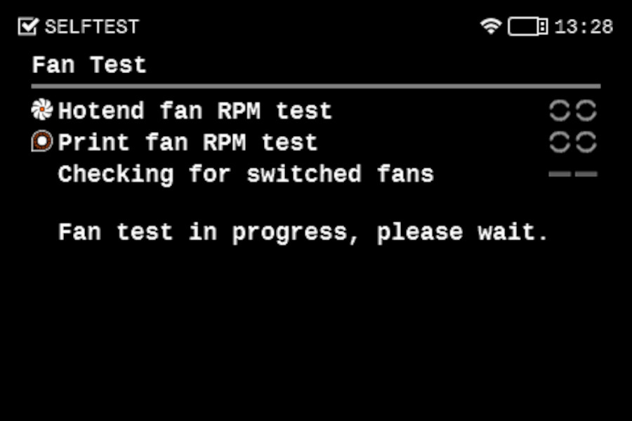
Fan test
The fans selftest checks if they are properly connected, if nothing is blocking their way, and if their connections are not switched on the dwarf board. For that, the firmware measures the fans` RPM, and they need to be between these values:
- Print fan: 5300 - 6799 RPM
- Hotend fan: 6800 - 8700 RPM
If one of the tests fails, you will see a red "x" near the failed part.
- Make sure that both of your fans are connected to the Dwarf board in their respective places.
- Check for any blockage that could prevent either of the fans from spinning.
- Try removing the fan shroud and make the test again. If it passes without the shroud, install the fan shroud back and continue the test. There is no need to remake the test with the shroud.
 |
Y and X axes test
The printer can determine if the components are moving correctly along each axis.
If the X and/or Y axes do not pass the test, move the tool changer by hand in different directions, and check for resistance.
If the axes make a metal-on-metal sound, check if any of the balls from the rail fell. If you are not sure, take a video where the noise is clear, and send it to our カスタマーサポート.
Z alignment calibration
This step will align the heatbed by moving the Z axis up and down. If there is an issue with this test, try checking the trapezoid nuts, the heatbed alignment, and if the Z-axis lead screws are not bent or wobbly.
If the issue persists, try slightly loosening the screws on the z-axis bearing housing. Do not remove them, but make sure that the screws are not tightened.
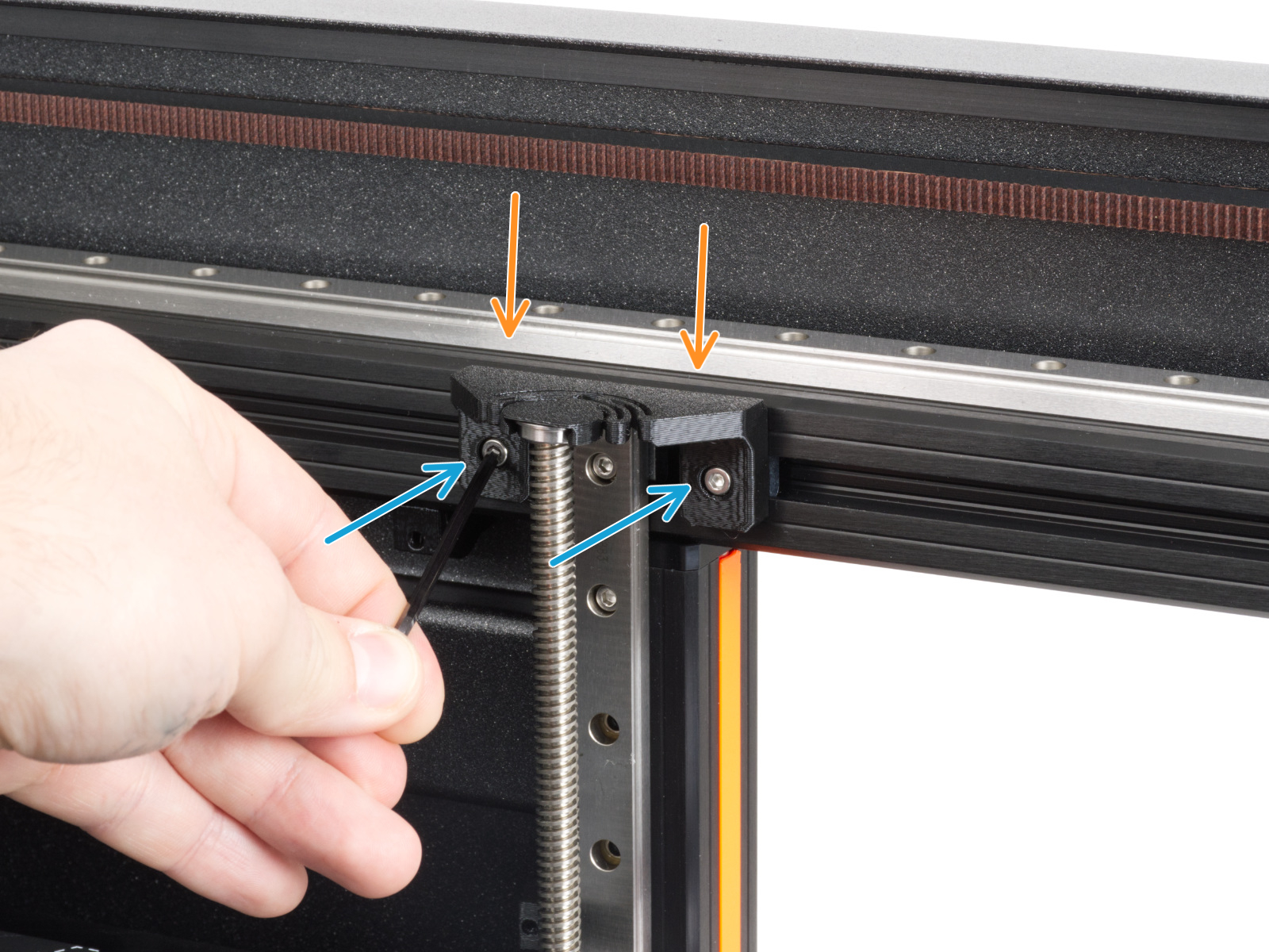
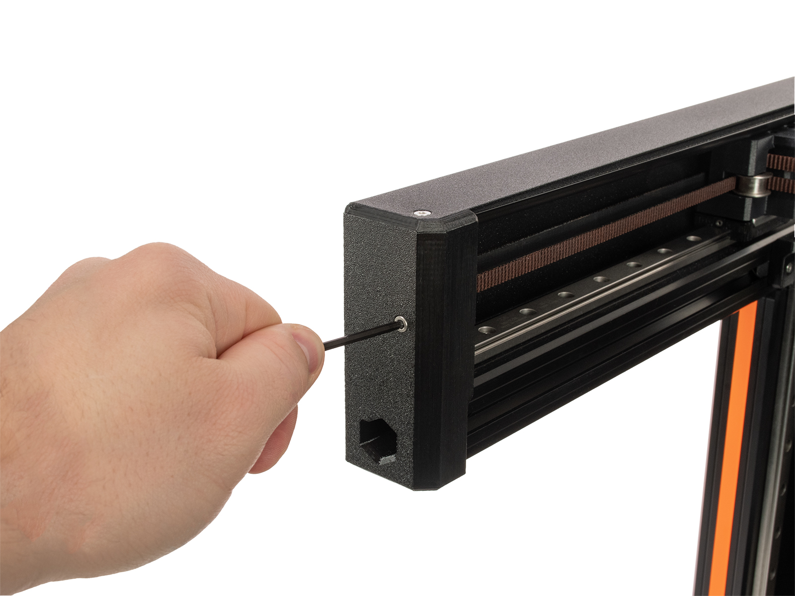
Dock Position calibration
This part of the selftest determines the dock position for picking and parking tools. It is recommended to open the step-by-step guide for easier understanding. If the light on the print head is yellow, don't hesitate to contact our カスタマーサポート.
If the error ドック位置が不整合 #17103 (XL) shows, follow the troubleshooting steps.
If the calibration ends with a red "x", it means that the tool could not successfully find the dock. Make sure that the cable bundle on the tool head is not bent or impairing its movement. Check the dock position: if it is not wiggling, if the metal part of the dock is perpendicular to the extrusions, and if they are fully seated in the extrusions with no gaps, and that the metal profile that holds the extruders is all the way to the left. If you see any of those things, try loosening the dock and tightening it again.
 |
Loadcell test
A functioning loadcell is fundamental for the Original Prusa XL to detect that the nozzle is close enough to the steel sheet for printing, and to avoid damage that would be caused by the nozzle digging into the steel sheet.
- Make sure that the loadcell is correctly connected to the Dwarf board.
- Make sure that the surface the printer is on is as stable as possible. Any form of vibration propagated to the surface under the printer, or a not fully stable surface under the printer might cause a false reading on the loadcell, causing it to fail the selftest. This includes other printers printing near the XL during the selftest.
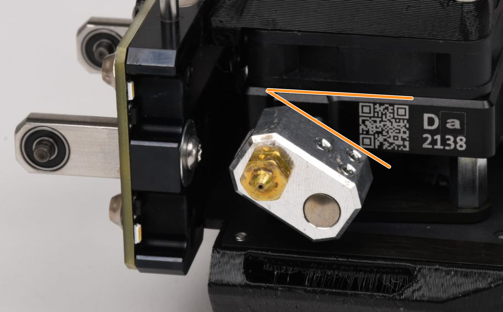
Nozzle diameter confirmation
The initial Original Prusa XL units were shipped with the 0.6 mm nozzles but then started being shipped with the 0.4 mm nozzles. Check which one is yours based on this guide and confirm it in the menu.
Z axis test
This part of the selftest checks the full length of the Z-axis. Note that this test uses the Loadcell, so if you have any issues with the Loadcell calibration it will also not pass. If no problems are observed in the Loadcell, check if anything is blocking the heatbed from moving across its full track or if something is touching the extruder.
Nozzle heater test
This test will heat all the heaters to see if they are working. If any of the heaters show an error, try swapping the heater cable with one of the other tool heads. See if the error will be transferred to the other toolhead, or if it will remain in the same one. Then, do the same procedure with the thermistor. If in both cases the issue remains in the same tool head, the issue should be on the board. If the problem is transferred to the new tool head then the cable that was transferred needs to be replaced. Make a documentation of the problem, and send it to our カスタマーサポート.
Filament sensor
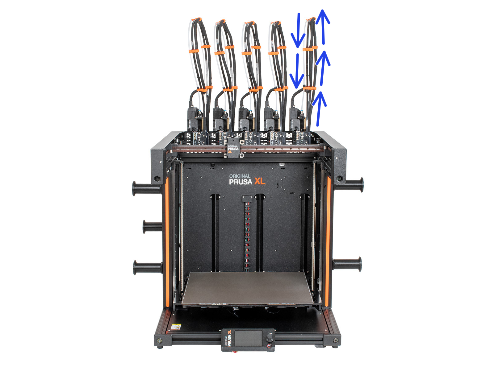
The Original Prusa XL is equipped with two filament sensors: the first one is located on the side, close to the input of the PTFE tube where you feed the filament. The second one is located in the extruder. Both filament sensors are necessary for the correct filament retraction: when the sensor on the side detects that the filament has run out, the filament will be retracted in time.
Usually, any issues in the sensor are caused by having the springs that trigger the sensor being stuck with dirt and filament strings. In case this happens, clean the side filament sensor or the tool head filament sensor.
If that does not help, make sure that the tool head filament sensor is connected to the Dwarf board, and that the side filament sensor is well connected to the sandwich board.
Tool offset calibration
The multi-tool format of the XL makes this calibration necessary to ensure that, when there is a tool change, the new tool will correctly continue the print. If one of the tools deviates too far from the expected range compared to the first tool head, an error will appear and the calibration will be interrupted. It is important to note that all tools are adjusted based on the first tool. So if there is an issue with the second to fifth tool, it might be due to a problem with the first tool calibration.
If any filament is loaded, unload it before starting this calibration.
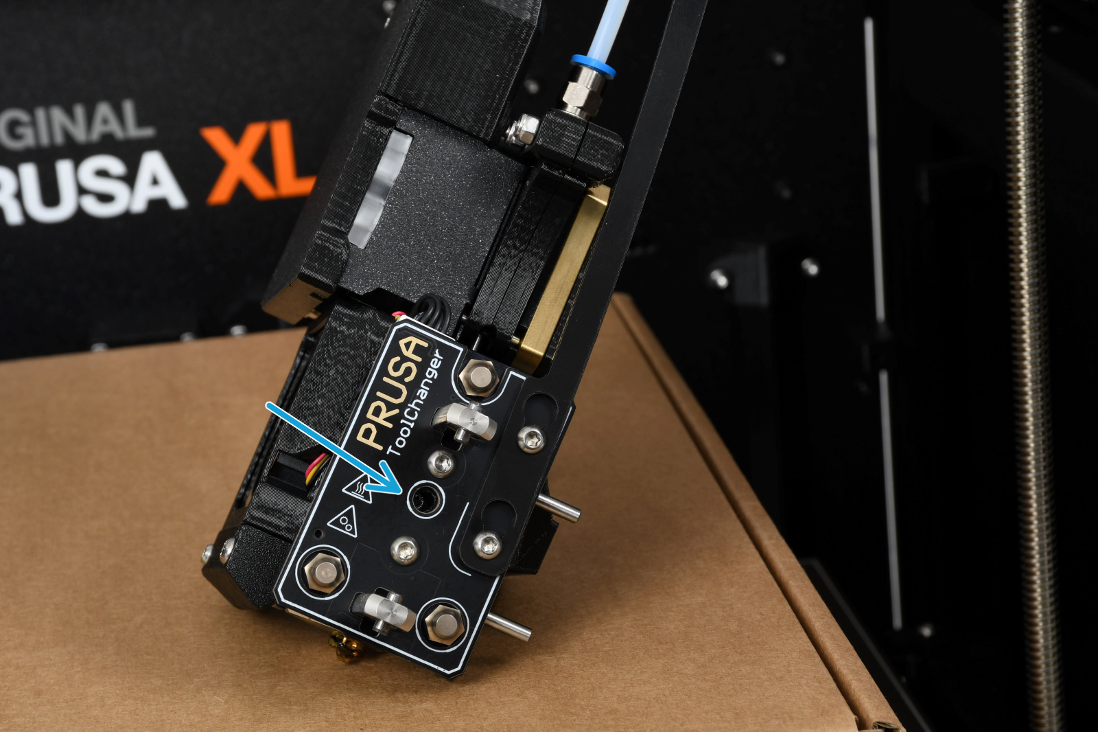
If the calibration fails, first check the movement of the tool head after it is picked. The flexible plate that holds up the cable bundles and the PTFE needs to be in a straight line so that the cables are not bent or falling to the sides.
Then, check the nozzle. If the nozzle is too low it will hit the plastic part of the calibration pin. For testing, you can loosen the grub screw that holds the nozzle and push it up. After making sure it is all the way to the top, tighten the screw again. If you use an adapter, check the gap between the nozzle and the heater block. Also, check the heaterblock angle.
 |  |
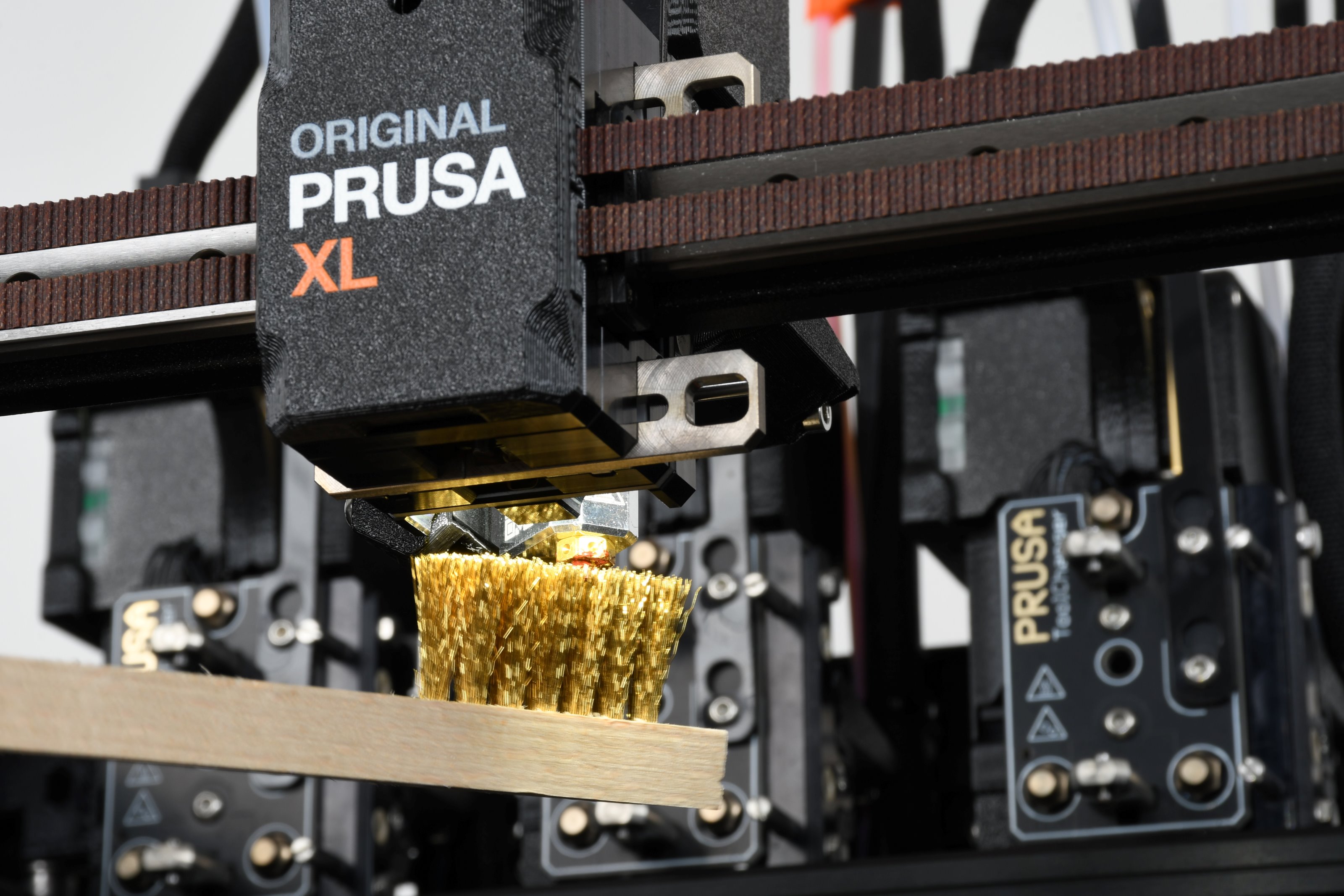
If you are doing this calibration after having used the printer, make sure that the outside of the nozzle is clean. To clean it, go in the printer menu to Control -. Pick/Park Tool -> Pick Tool #. Then, go in the menu to Control - Temperature - Nozze, and set the temperature for the one used in your last print. After it is heated, use a brass brush to clean the outside of the nozzle.
If even after doing all of the steps above the tool offset still fails, try doing a hard factory reset. This will require you to go through the entire selftest process again. You can also remove the plastic from the calibration pin to test if the calibration will pass.
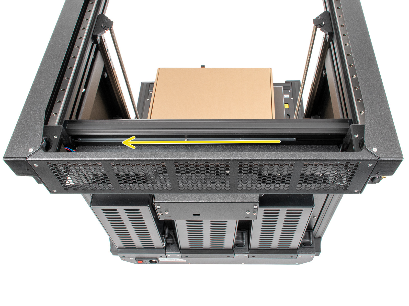
Bed heater test
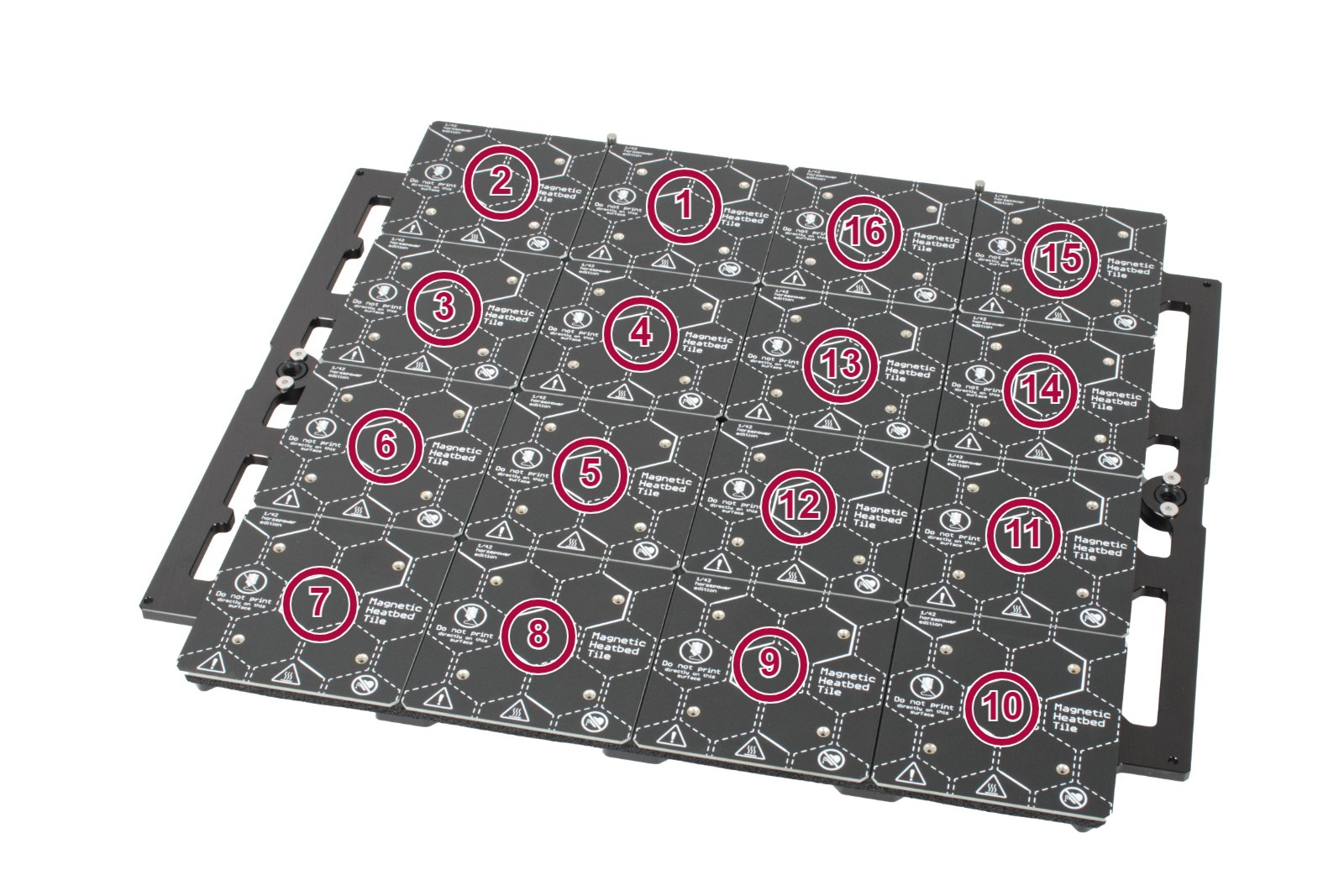
This part of the Selftest will test the heatbed heating. If you have an issue during this calibration, first make sure that the steel sheet is on the heatbed, or is added to the heatbed after it reaches around 50 ºC. Then check the cables under the heatbed. Make sure none of them are crimped, especially near the connectors. Gently tug the cables and see if they come off.
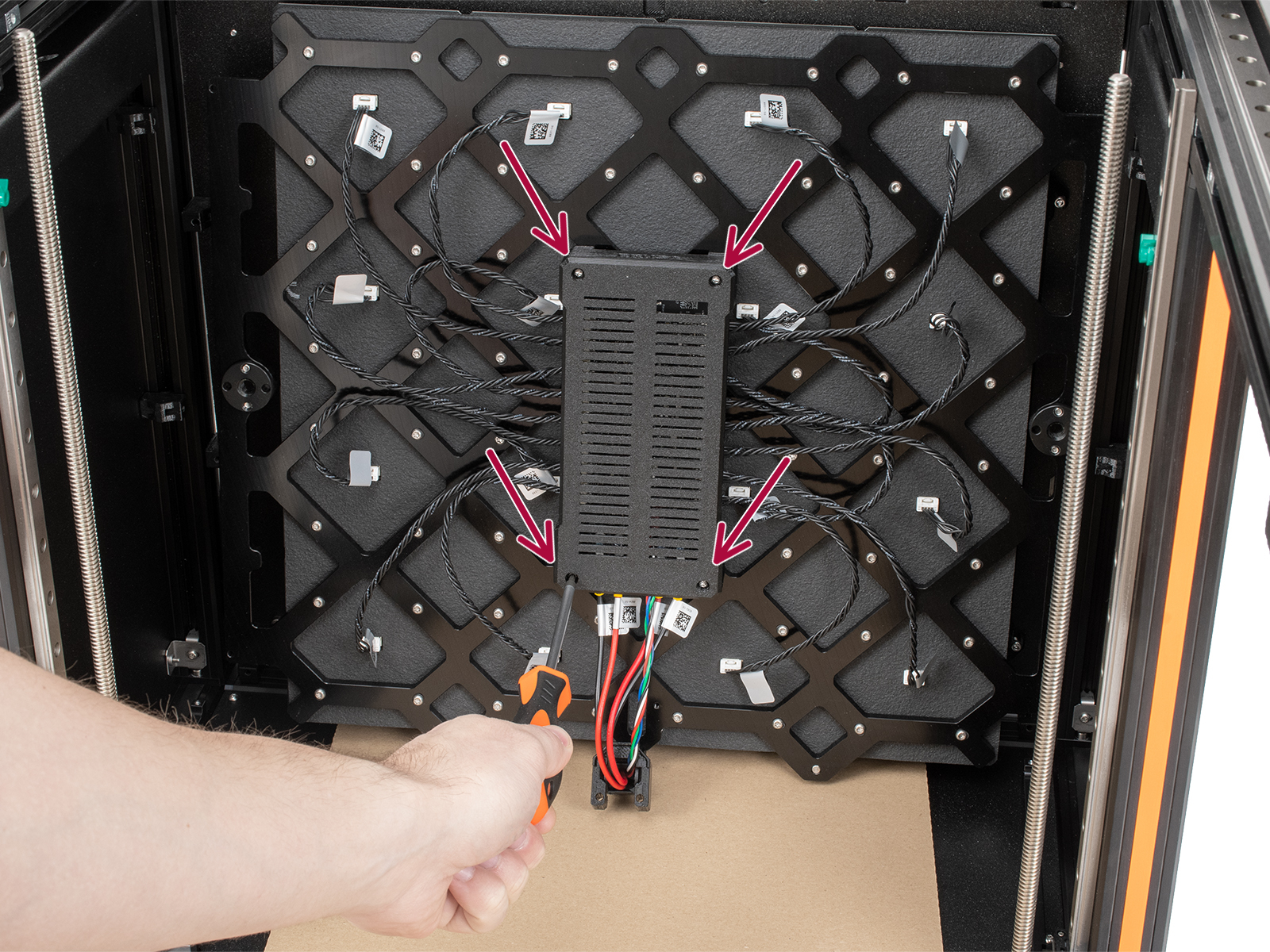
If the screen shows an error related to a specific tile, first identify the tile using the image above. Then, check the connectors on both sides of the cable. Open the bed controller case by unscrewing the four screws shown below, and see if there are any burn marks around the connectors.
Phase stepping calibration
The last part of the tests is the phase stepping. For this, make sure that you are not touching the printer and that no other printers are running on the same surface as the XL. You can read more about it here: フェイズステッピング (XL).
Comments


Still have questions?
If you have a question about something that isn't covered here, check out our additional resources.
And if that doesn't do the trick, you can send an inquiry to [email protected] or through the button below.