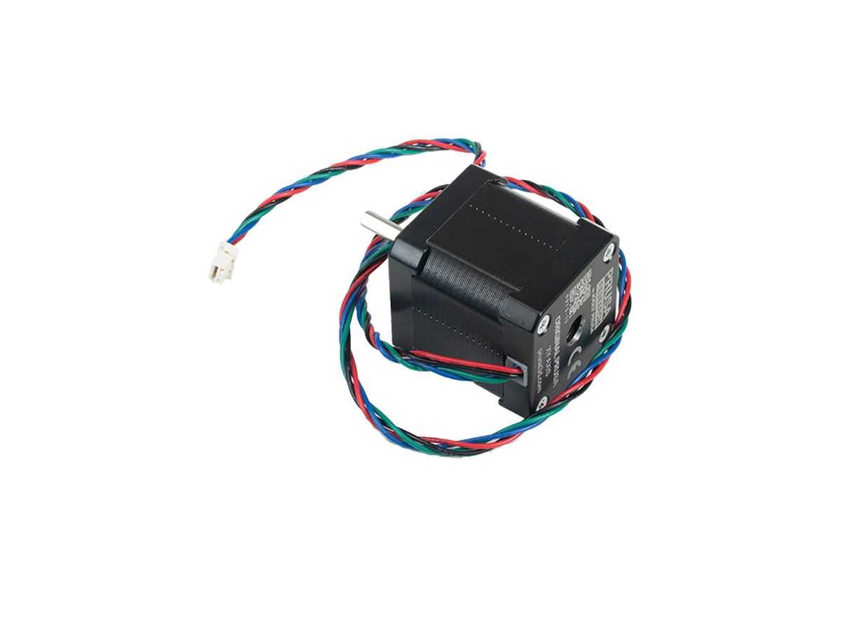
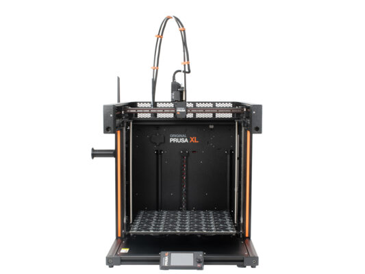
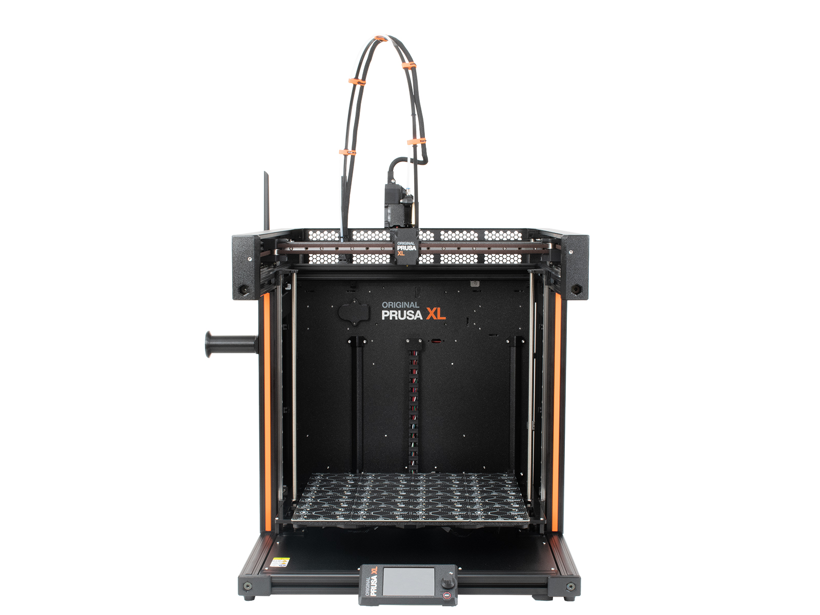
EN
  • Čeština
  • Italiano
  • Deutsch
  • Polski
  • Français
Login

How to replace a XY motor (XL)

Menu

How to replace a XY motor (XL)

How to replace a XY motor (XL)
Relevant for:
Last updated 12 days ago
How to replace a XY motor (XL)
 Difficulty
Moderate
 Steps
35
 Available languages
CSPLDEITFR
Introduction
Introduction
Introduction
This guide will take you through the replacement of the XY motor on the Original Prusa XL.
The following instructions are compatible with all Original Prusa XL versions.
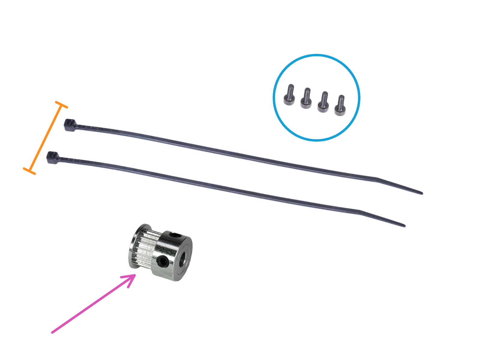
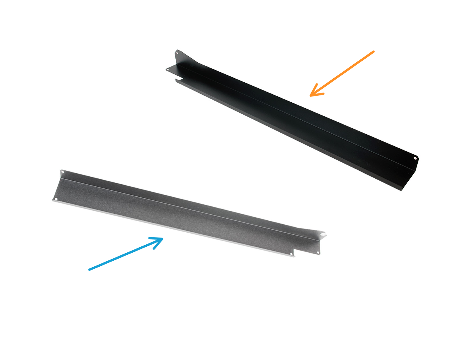
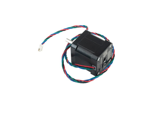
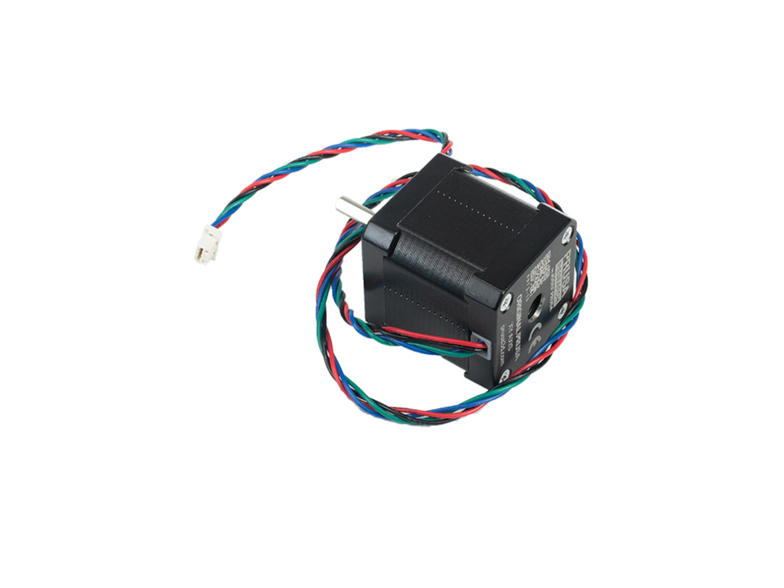
All necessary parts are available in our eshop prusa3d.com.
Note that you have to be logged in to have access to the spare parts section.
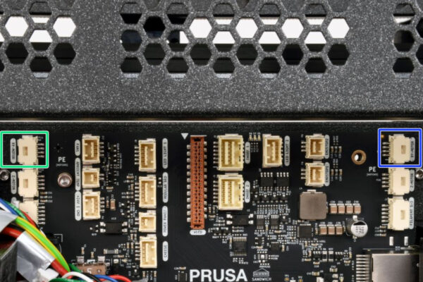
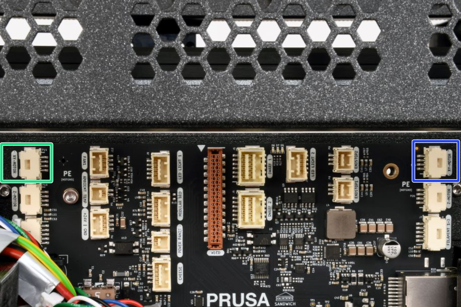
This manual is for both XY motors on the XL printer.
Necessary tools
Necessary tools
Necessary tools
Necessary tools
For this guide, please prepare: 
T10 screwdriver or key
2.5mm Allen key
2.0mm Allen key (this tool is not included with the Original Prusa XL)
Cable cutter (this tool is not included with the Original Prusa XL)
Zip ties (2x)
Printer preparing
Printer preparing
From the rear side, turn the power switch OFF (symbol "O").
Unlug the power cable.
Wi-fi antenna holder versions
The upcoming steps will vary based on the location of the Wi-Fi antenna on your printer.
Check the position of the antenna on your printer and follow the corresponding instructions:
Side mount: If the Wi-Fi antenna is on the left side of the printer (viewed from the front), proceed to Disconnecting the 1st and 2nd Nextruder cables
Rear mount: If the antenna is located at the top center on the back of the printer, proceed to the next step Detaching the Wi-Fi antenna
Detaching the rear Wi-Fi antenna
This step is specific to printers equipped with a Wi-Fi antenna located on the rear. If you have a version of the printer with an antenna on the side, skip this step.
Turn the printer, so the back side of the printer is facing you.
Locate the Wi-Fi antenna connector in the middle of the printer.
Loosen the Wi-Fi antenna from the antenna connector and set it aside.
Detaching the side Wi-Fi antenna
This step is specific to printers equipped with a Wi-Fi antenna located on the side.
Looking from the printer rear, the side antenna is located on the right side.
Loosen the side antenna to detach it from its holder, and set it aside.
Loosening the belt
Loosening the belt
Loosening the belt
Using the 2.5mm Allen key, release the M3x22 screw on both sides of the printer, both where the motor is replaced and the opposite side.
Attempt significantly loosening the belts, by the same amount on either side. If not, it will be possible to re-align the belts later on.
Loosening this screw loosens the belt and its tensioner with the idler pulley.
There is no need to completely loosen or remove the M3x22 screw, as long as the belt is significantly loose.
Removing the side coreXY cover
Using a Torx screwdriver, remove 5x M3x6cT screws
Slide out the side coreXY cover.
The LED panel is now exposed, avoid damaging it.
Removing the electronics cover
Turn the printer, so the back side is facing you.
Using a T10 Torx key, loosen four screws securing the electronics cover.
It is not necessary to fully remove the screws.
Remove the electronics cover by sliding it upward.
After open the electronics box, you can see one of the electronics options depending on the variation of your XL printer:
Single-Tool | Dual-Head - single board electronics.
Five-Head - there is an extra board for 3rd, 4th and 5th Nextruder cables.
Disconnecting the antenna cable
This step is necessary only for printers equipped with a Wi-Fi antenna located on the back.
Locate and carefully unplug the Wi-Fi connector.
Single-Tool, Dual-Head 
Five-Head - connected on the bottom electronics board. 
Disconnecting the 1st and 2nd Nextruder cables (rear antenna)
Proceed with this step for the printer version with rear antenna. If your printer has the antenna on the side, skip to the next step.
Each connector has a safety latch. It is necessary to press the latch before disconnecting. Otherwise, the connector may get damaged.
Be careful, do not damage the Wi-Fi antenna cable.
Loosen the two screws on the cover slightly. There's no need to completely remove them. Slide the cover to the right and take it off from the printer.
Push the safety latch and disconnect the first Nextruder cable from the upper slot labeled DWARF 1.
Push the safety latch and disconnect the second Nextruder cable from the lower slot labeled DWARF 2.
Push the cover to the right and remove it from the printer.
Disconnecting the 1st and 2nd Nextruder cables (side antenna)
Proceed with this step if the antenna is installed on the printer side.
Each connector has a safety latch. It is necessary to press the latch before disconnecting. Otherwise, the connector may get damaged.
Loosen the two screws on the cover slightly. There's no need to completely remove them. Slide the cover to the right and take it off from the printer.
Push the safety latch and disconnect the first Nextruder cable from the upper slot labeled DWARF 1.
Push the safety latch and disconnect the second Nextruder cable from the lower slot labeled DWARF 2.
Uncovering the electronics
Using a T10 screwdriver, loosen the four M3x5rT screws. Do not throw them away! We'll use them later.
Carefully pull out the rear-cable-management-upper.
Disconnecting the XY motor cable
Be careful and avoid damaging the cables using the cable cutter!
Using a cable cutter, carefully cut the two zip ties on the side of the motor to be replaced.
The procedure is equivalent for either side.
Each connector has a safety latch. It is necessary to press the latch before disconnecting. Otherwise, the connector may get damaged.
Disconnect the motor cable from the motor that will be replaced.
Left XY-axes motor
Right XY-axes motor
Removing the XY motor
Using the 2.5mm key, remove 4x M3x8 screws.
Push the motor upward when removing the last screw.
Take out the belt loop from the pulley attached to the motor.
If needed, slightly loosen the belt further from both the printer sides, ideally by the same amount.
Keep the belt looped.
Remove the motor with its attached pulley from the printer side.
Thanks to the belt being loose, there is enough space for the motor to slide out.
Removing the XY motor pulley
Using the 2.0mm Allen key, loosen 2x set screws from the pulley 20t attached to the motor shaft.
Be careful, do not lose the set screws!
Slide out the pulley 20t from the motor shaft.
New motor: parts preparation
For the following steps, prepare the following parts:
XY-axes motor (1x)
M3x8 screw (4x)
Zip tie (2x)
Pulley 20t (1x)
Assembling the motor pulley
The pulley position differs whether it's assembled on the XY left or XY right motor.
On either motor, install the pulley so that one set screw is aligned with the flat part of the motor shaft.
XY motor right
Note the orientation of the pulley. The teeth are above the set screws.
Install the pulley flush with the top edge of the motor shaft.
XY motor left
Note the orientation of the pulley. The teeth are below the set screws.
Install the pulley 2.5mm higher than the start of the flat part of the motor shaft. Use the 2.5mm Allen key for reference.
Alternatively, measure the distance between the beginning of the motor shaft and the pulley, 3.6mm.
Tighten both set screws using the 2.0mm Allen key.
Installing the XY motor
Insert the motor with its attached pulley into its housing.
The motor cables have to be oriented towards the center of the printer.
Locate the belt loop.
Loop the belt around the motor pulley.
Using the 2.5mm Allen key, tighten 4x M3x8 screws.
Lift the motor while tightening the screws.
Securing cables (rear-left)
If you are replacing the right XY motor, follow this step. If you are replacing the XY motor on the left side, skip this step and proceed with the next one.
ATTENTION: Do not overtighten the zip ties! Otherwise, you risk damaging the cables.
Under the cables, there are two perforations in the metal sheet.
Insert two zip ties through the perforations in the metal sheet to secure the cables. Tighten them gently.
Cut the excess of the zip ties.
Securing cables (rear-right)
If you are replacing the XY motor on the left side, follow this step.
ATTENTION: Do not overtighten the zip ties! Otherwise, you risk damaging the cables.
Insert two zip ties through the perforations in the metal sheet to secure the cables. Tighten them gently.
Cut the excess of the zip ties.
Overview of electronics wiring
Before proceeding to the next step, check the cable connections according to the picture.
Right XY motor cable
Left XY motor cable
In the second picture the full wiring diagram is shown. Only the 'Motor XY - left' and 'Motor XY - right' have been disconnected and reconnected during this guide.
Double-check all the connections before proceeding to the next step.
Covering the electronics: parts preparation
For the following steps, please prepare:
Rear-cable-management-upper (1x)
XL-buddy-box-cover (1x)
M3x5rT screws (4x)
Either of the following two parts depending on the antenna mount position:
Antenna-holder with antenna cable (1x) rear-antenna version
Rear-cable-management plug (1x) side-antenna version
Covering the electronics
Be careful, don't pinch any cables.
Gently attach the Rear-cable-management-upper on the rear side.
Make sure that no cable is pinched in the plastic covers.
Make sure that the metal cover does not pinch the motor cable.
Secure it with four M3x5rT screws using a T10 screwdriver.
If your printer has its antenna on the side, check if the XL-rear-cable-management-plug is installed.
Loosen two bolts using the T10 screwdriver, and remove the XL-rear-cable-management-plug.
Connecting the 1st and 2nd Nextruder cables
Connect the first Nextruder cable to the upper slot labeled DWARF 1.
Connect the second Nextruder cable to the lower slot labeled DWARF 2.
If your printer had the antenna located on the side, proceed with the following point.
Attach the cover (xl-rear-management-plug) onto the screws. Push the cover all the way to the left and tighten the screws.
If your printer had the antenna located on its rear side, proceed to the next step.
Installing the Wi-Fi antenna cover (rear antenna)
This step is valid only if your printer has its Wi-Fi antenna on the back of the printer. If you have the antenna on the side of the printer, proceed to the next step.
Push the antenna cable through the opening in the cable cover (metal sheet) and guide it behind the cover to the electronics box.
Attach the antenna-holder on the screws and push the cover to the left and tighten the screws.
Covering the XL buddy box
Be careful, do not pinch any cables!
Put the XL-buddy-box-cover back on the printer.
On the five-head XL, check the Nextruders cables, they have to be inside the cutout in the cover.
With a T10 key tighten the four screws.
Installing the side panel: parts preparation
For the following steps, please prepare:
M3x6cT screw (5x)
Either of the following two parts depending on which side was uncovered:
Cover-corexy-right (1x)
Cover-corexy-left (1x)
Installing the side panel
Slide in place the cover-corexy-right or cover-corexy-left
Using the T10 screwdriver, tighten 5x M3x6cT screws to fix the cover in place.
Tightening the belt
Tightening the belt
If not aligned yet, align the M3x22 screw with the hole in the tensioner.
Using the 2.5mm Allen key, tighten the M3x22 screw.
Follow the dedicated article to readjust your belt tension, referring to the 'Belt tuner' and 'Alignment' paragraphs.
Do not worry if the belt tension is not yet perfectly tuned after this intervention. You can resume the belt tension adjustment at a later time with the printer assembled and running.
Switching the printer on
Turn the printer's front side facing you.
From the rear side, plug in the power cable.
Turn the power switch ON (symbol "I").
Performing the Calibration Wizard
After the printer starts up, the screen prompts for the printer test and setup wizard.
The wizard will test all important components of the printer. The whole process takes a few minutes. Some parts of the wizard require direct user interaction. Follow the instruction on the screen.
NOTE: While testing the axes, make sure that there is nothing in the printer that is obstructing the movement of the axes.
WARNING: Do not touch the printer during the wizard unless prompted! Some parts of the printer may be HOT and moving at high speed.
Follow the steps in the dedicated manuals, specific for your version of Original Prusa XL.
Good Job!
Good Job!
Well done, you successfully replaced the XY-axes motor on your Original Prusa XL!
Was this guide helpful?

Comments

Still have questions?

Still have questions?

If you have a question about something that isn't covered here, check out our additional resources.
And if that doesn't do the trick, you can send an inquiry to [email protected] or through the button below.

Contact us