JA
  • English
  • Italiano
  • Deutsch
  • Polski
  • Français
Login

How to replace a print fan (MK4S / MK3.9S)

How to replace a print fan (MK4S / MK3.9S)

How to replace a print fan (MK4S / MK3.9S)
Relevant for:
Last updated 20 days ago
How to replace a print fan (MK4S / MK3.9S)
 Difficulty
Moderate
 Steps
20
 Available languages
ENPLDEITFR
Introduction
Introduction
This guide will take you through the Print fan replacement on your Original Prusa MK4S or MK3.9S.
All necessary parts are available in our eshop prusa3d.com.
Note that you have to be logged in to have access to the spare parts section.
Preparation
Preparation
Preparation
始める前に、プリンタのエクストルーダーがX軸とZ軸の中央にあることを確認してください。
Unload a filament, if it is loaded.
プリンタの電源を切り、電源から取り外します。
Removing the covers
Removing the covers
Removing the covers
Remove the Loveboard-cover from the extruder.
Remove the M3x30 screw holding the Fan-door-hinge part.
Remove the Fan-door-hinge plastic part.
Disconnecting the hotend

Disconnect the hotend heater connector. 

Dislodge the cable from the groove in the x-carriage part.

Note that there is a safety latch which must be pressed in order to remove the connectors. Proceed carefully to prevent damaging the connectors.
Proceed carefully to prevent damaging the connectors.

Disconnect the hotend thermistor connector.

Dislodge the cable from the groove in the x-carriage part.

Removing the hotend
Removing the hotend
Removing the hotend
Remove the thumb screws fixing the hotend in place.
Remove the hotend assembly from the extruder.
Be careful not to damage the cables.
プリントファンを取り外す
プリントファンを取り外す
プリントファンを取り外す
プリントファンを取り外す
Disconnect the print fan connector.
Note that there is a safety latch which must be pressed in order to disconnect the connector.
Dislodge the print fan cable from the groove in the x-carriage part.
Remove the four M3x5rT screws from both sides of the fan-holder.
Print fan disassembly part 1
Remove the print fan assembly from the extruder by sliding it out. Watch out for the cable.
Remove the M3x5rT screw hoding the fan-shroud.
Remove the fan shroud.
Print fan disassembly part 2
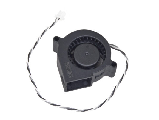
Remove the two 3x8sT screws.
Remove the fan-case-cover.
Remove the old print fan and its cable from the plastic part.
Print fan assembly
Print fan assembly
Print fan assembly
Insert the MK4S print fan blower into the print fan blower case.
ファンケースのケーブルチャンネルにプリントファンブロワーケーブルを通します。
ファンをファンケースカバーで閉じます。
3x8sTのネジ2本でカバーを固定します。
ファンシュラウドの組み立て
ファンシュラウドの組み立て
ファンシュラウドの組み立て
ファンシュラウドをプリントファンブロワーアセンブリに取り付けます。ファンシュラウドには2つの歯があり、ブロワーアセンブリには2つの長方形の穴があることに注意してください。
まず、長方形の切り込みに歯を差し込みます。
Close the Fan-shroud and secure it with the M3x5rT screw.
部品が壊れないように、適度な力で行ってください。
プリントファン・ブロワーアセンブリの取り付け
プリントファンブロワーアセンブリを取り、ファンホルダー左側の切り欠きにファンケーブルを通します。
ヒートシンク・ファンケーブルが既に通っているのと同じ切り欠きを使用します。
プリントファンブロワーアセンブリのサイドポケットをファンホルダの2つの「フォーク」にスライドさせます。
両方のパーツの穴が揃っていることを確認します。
Secure both parts together using four M3x5rT screws.
プリントファンブロワーの接続
プリントファンブロワーの接続
プリントファンブロワーの接続
プリントファンブロワーケーブルをXキャリッジのケーブルチャンネルに通し、コネクタをLoveボードの中央スロットに差し込みます。
ホットエンドアッセンブリーの組付け
ホットエンドアッセンブリーの組付け
ホットエンドアッセンブリーの組付け
ホットエンドアッセンブリーの組付け
Insert two thumb screws into the heatsink. Do not tighten them completely. Two turns are enough for now.
ヒートシンクの下側をよく見て、ホットエンドアセンブリ用の穴を見つけます。
ホットエンドアセンブリーチューブを穴に挿入し、全体をヒートシンクにスライドさせます。
ホットエンドアセンブリをヒートシンクに完全に押し込みます。ヒートシンクとノズルの真鍮部分の間に約 2 mm の隙間があるはずです。
While pushing the hotend assembly in, firmly tighten both thumb screws.
Avoid pinching any cable between the screws and the heatsink!
下側から、ホットエンドの向きが正しいことを確認します。Xキャリッジの切り欠きの間に収まるようになります。
ホットエンドケーブルの接続
ホットエンドケーブルの接続
ホットエンドケーブルの接続
ホットエンドケーブルの接続
ホットエンドサーミスタをX-carriageのケーブルチャンネルに通し、LoveBoardに接続します。
X-carriageのケーブルチャンネルにホットエンドヒーターを通し、LoveBoardに接続します。
Attaching the Fan-door-cover
Attach the Fan-door-cover hinge to its counterpart in the X-carriage. Holes in both parts must be aligned.
Fan-doorのヒンジにM3x30のネジを挿入します。ネジを一度完全に締めた後に、1/4回転緩めます。Fan-doorが自由に動くようにしてください。
LoveBoard: Wiring check
Before covering the electronics, check the connection of all cables. Click on high-resolution preview in the top left corner.
Close the idler mechanism if you haven't already done so.
LoveBoardをカバーする: 上部カバー
すべてのケーブルをエクストルーダーに押し付け、周囲にスペースを作ります。写真を参照してください。
Loveboard-cover をエクストルーダーの上にスライドさせます。そして下まで押し込んでください。カバーはX-carriage-backの裏側にある必要があります。
ケーブルを挟まないように注意してください!
2つのプラスチックカバーがぴったり合うことを確認します。
Finished
Finished
ファンの交換が終わりました。エクストルーダーが写真のように組み立てられていることを確認してください。
ファンの機能をテストするには、メニューから、「コントロール」>「キャリブレーションとテスト」>「ファンテスト」をご覧ください。
Was this guide helpful?

Comments

Still have questions?

Still have questions?

If you have a question about something that isn't covered here, check out our additional resources.
And if that doesn't do the trick, you can send an inquiry to [email protected] or through the button below.

Contact us