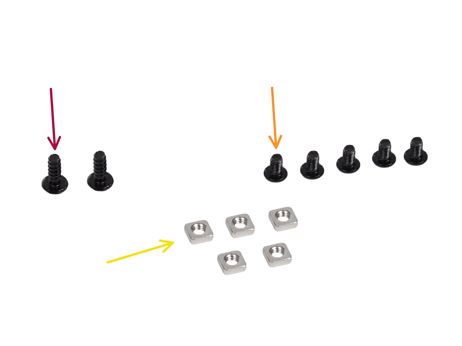
⬢For this chapter, please prepare:
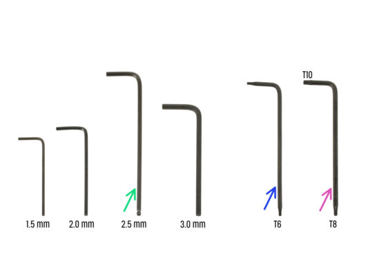
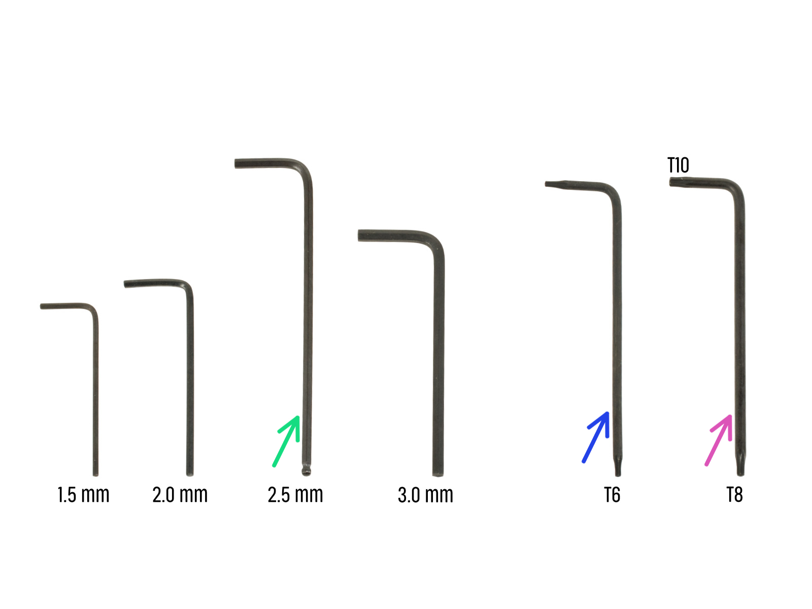
⬢2.5mm Allen key
⬢Torx key T6
⬢Torx key T10/8
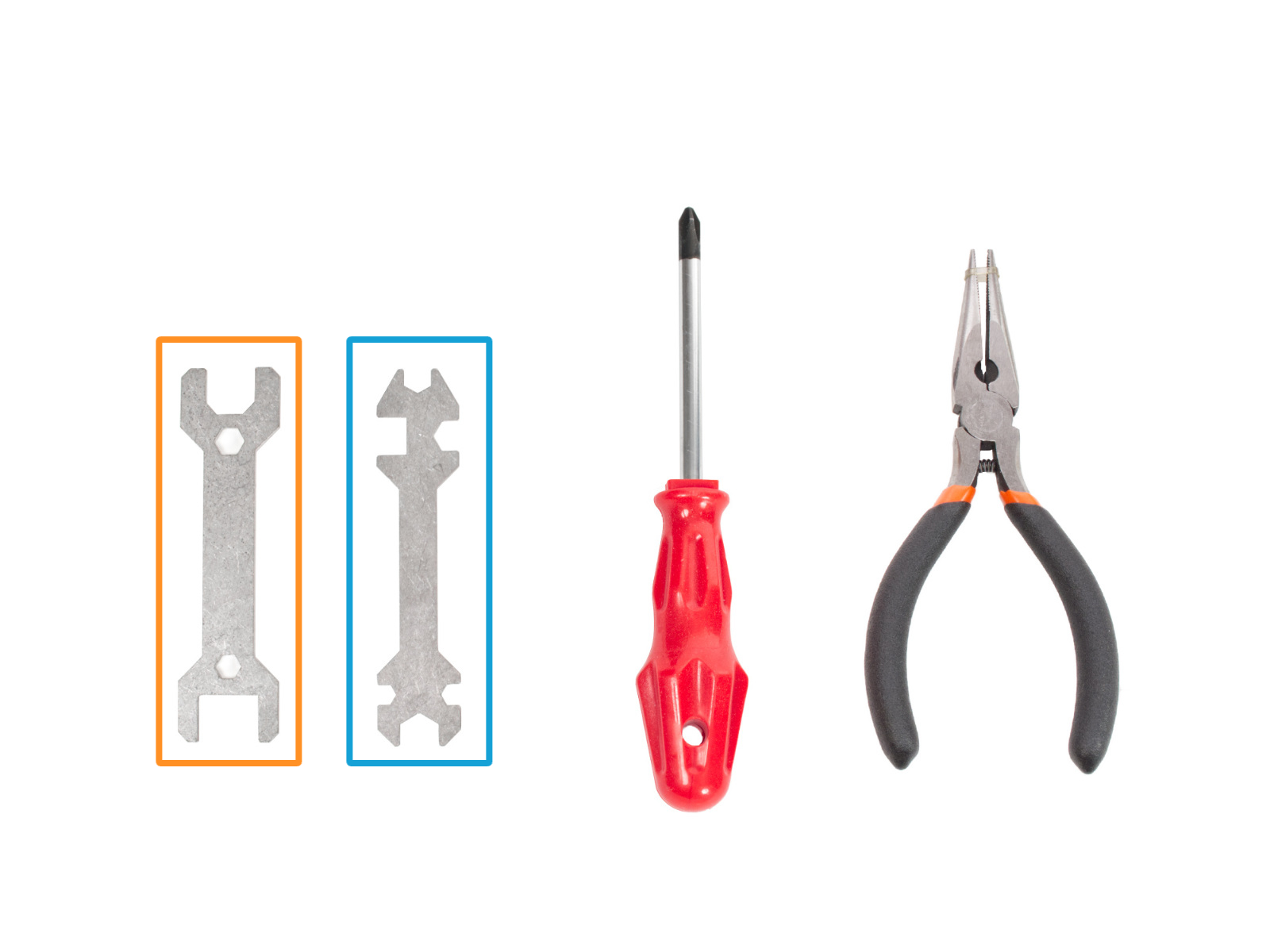
⬢Wrench 13-16
⬢Universal wrench
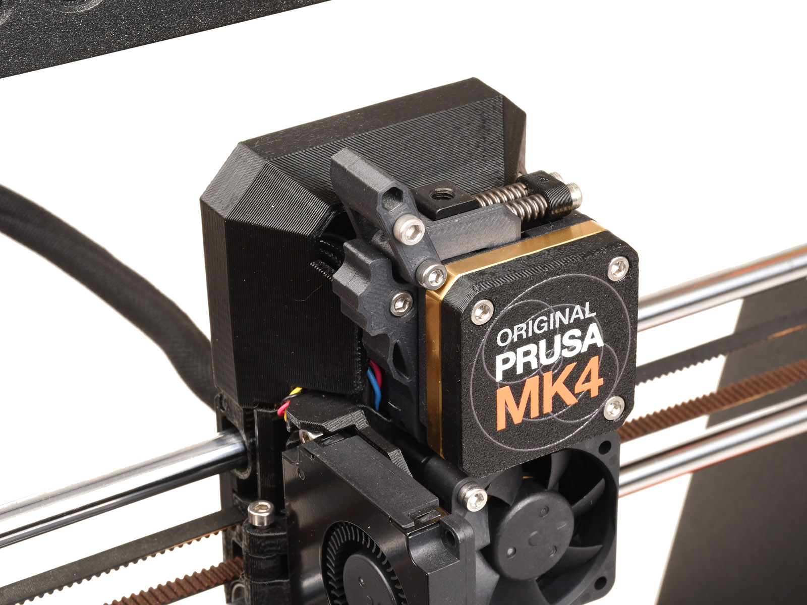

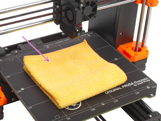


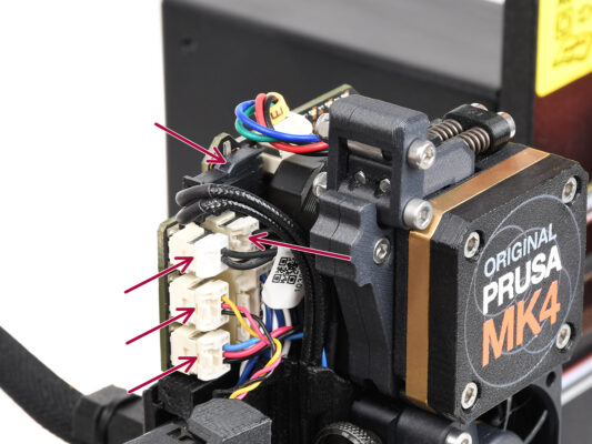

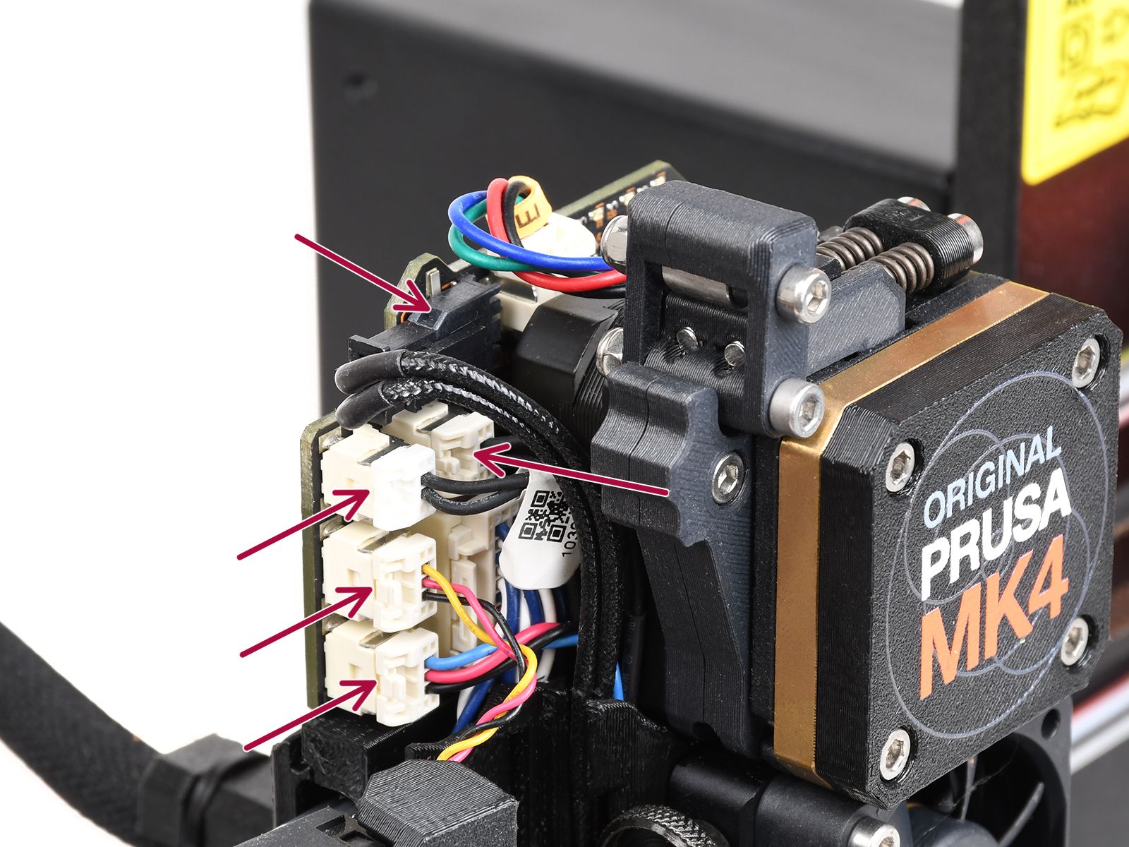
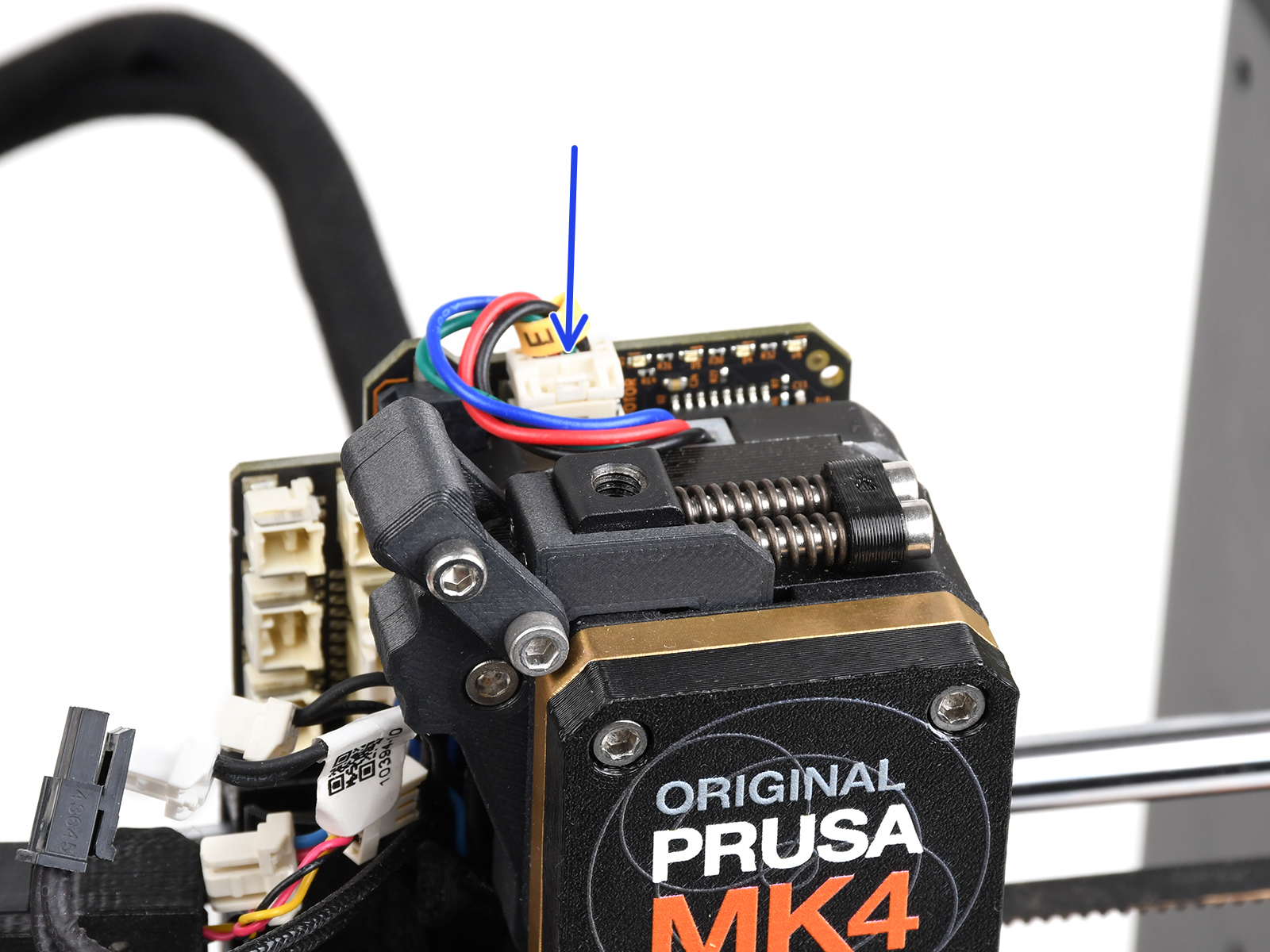


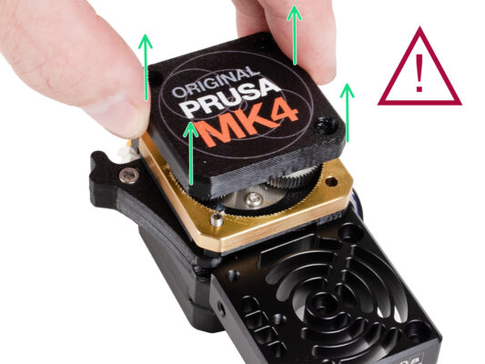
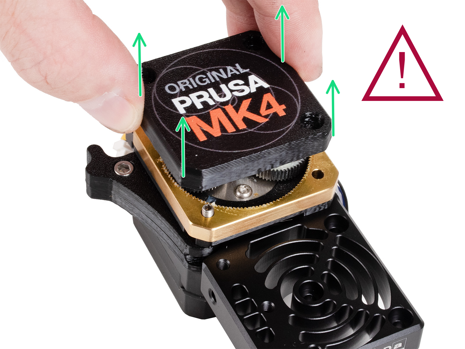


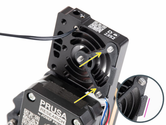

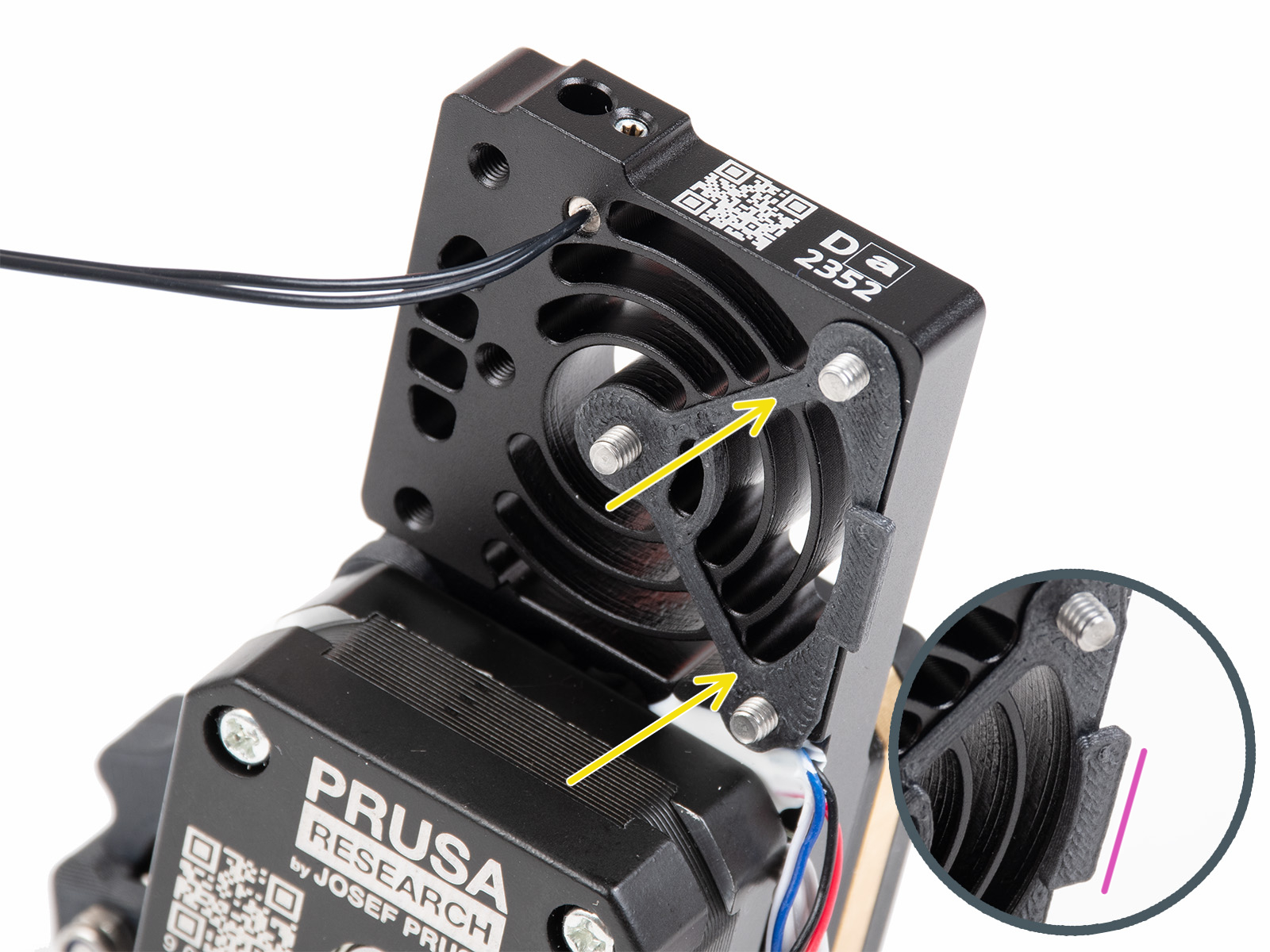
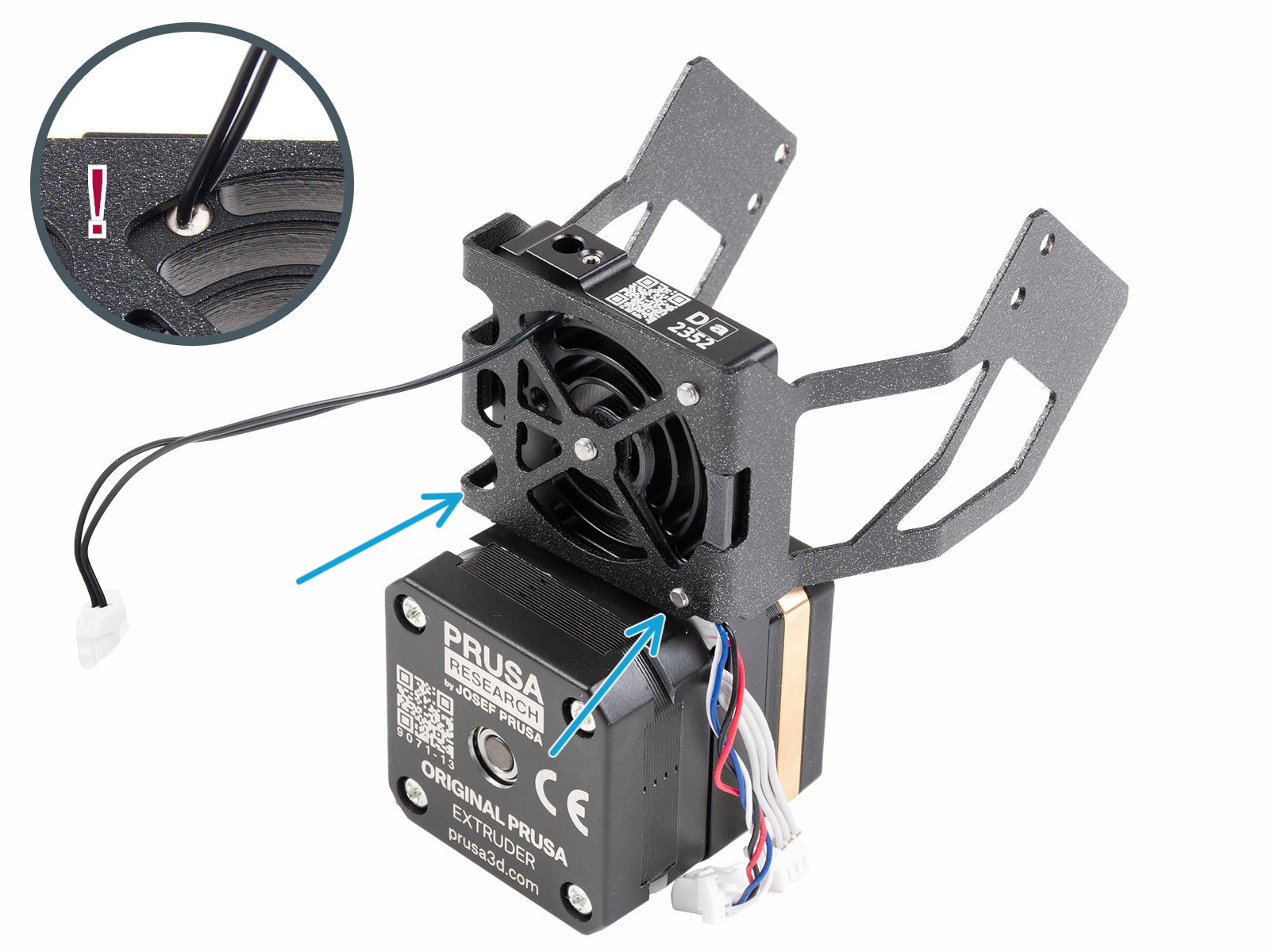
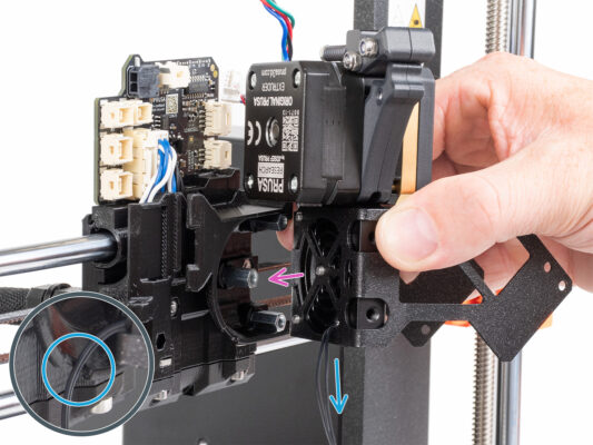
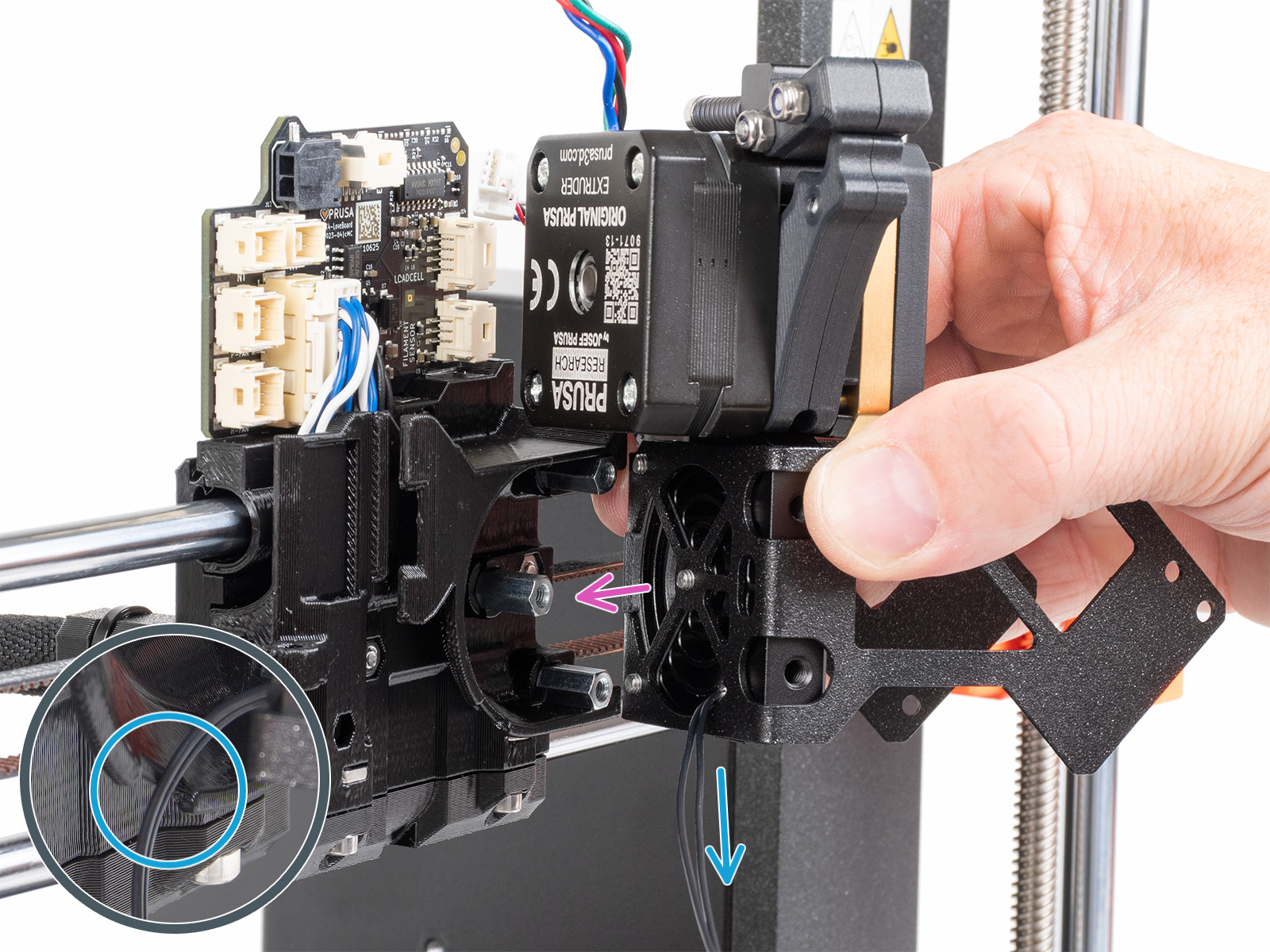
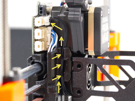
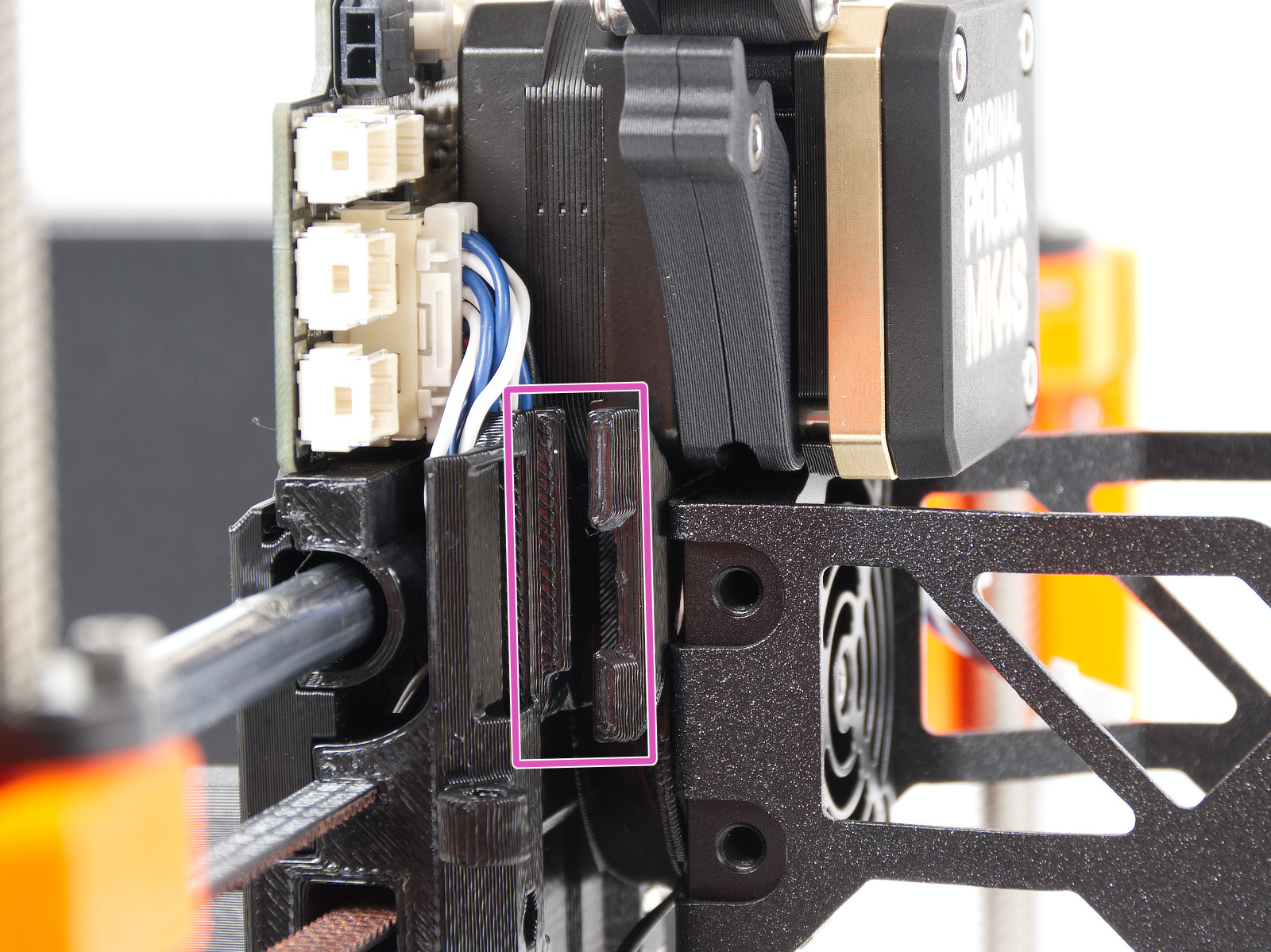
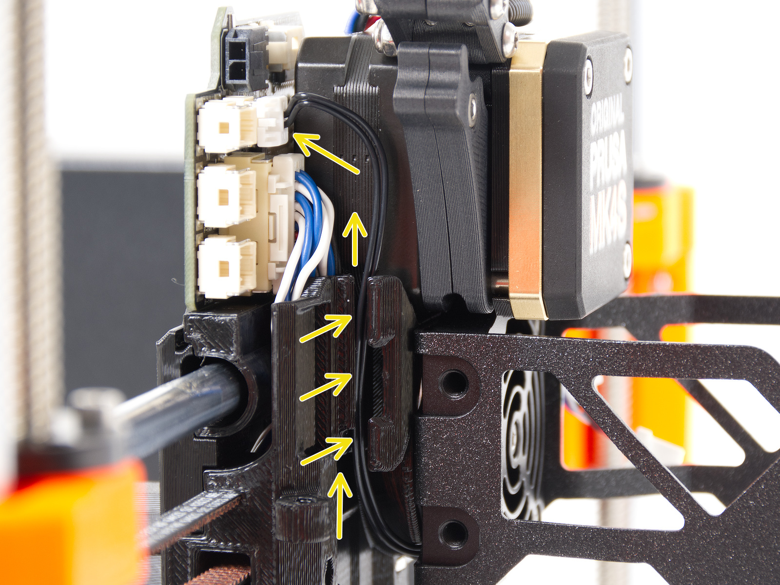
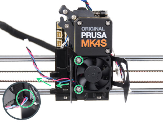
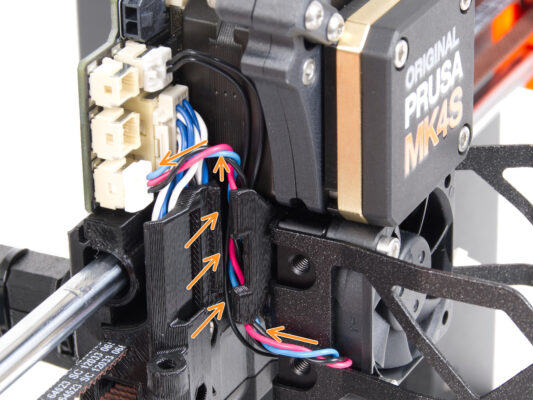
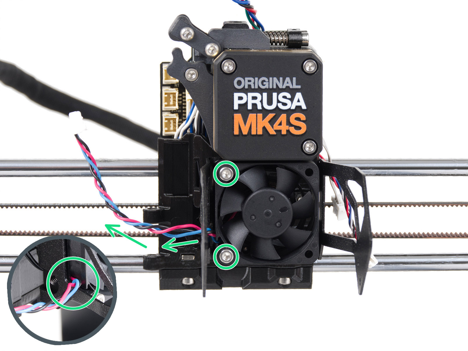
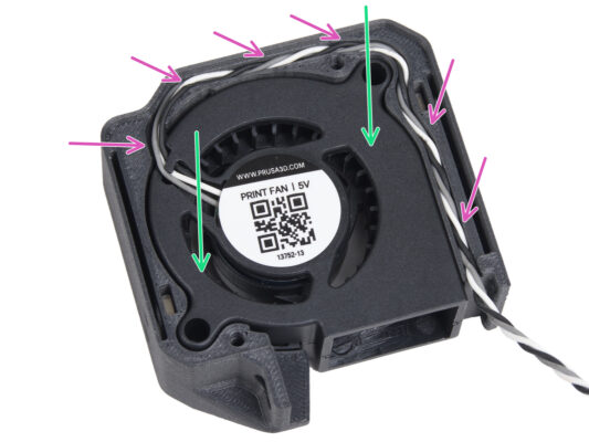
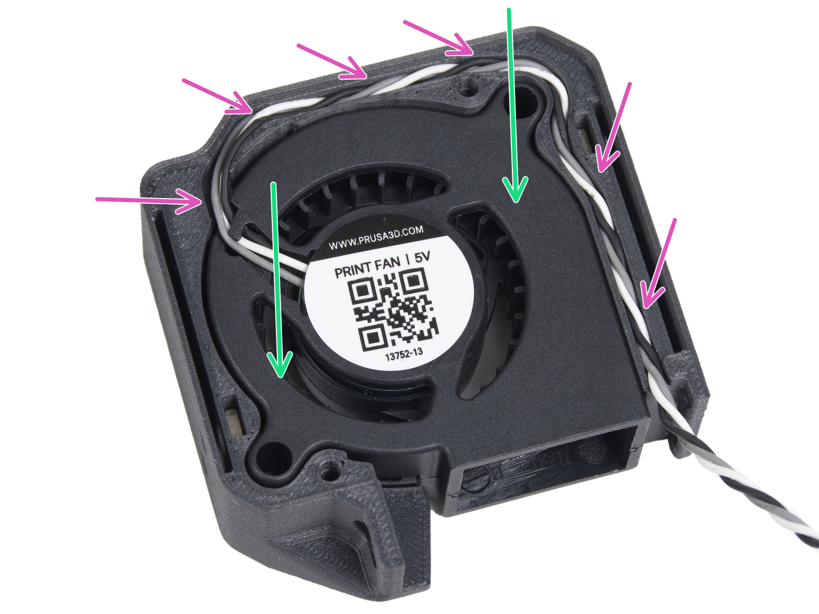
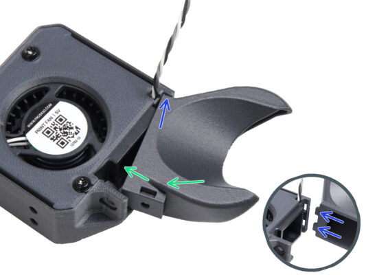
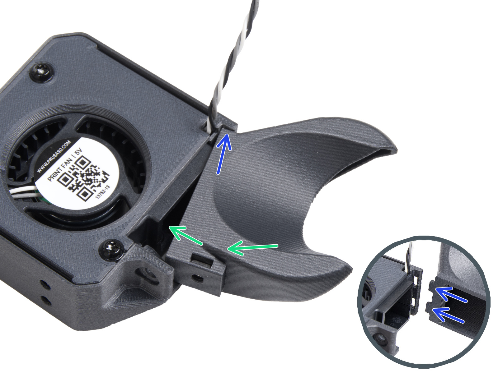
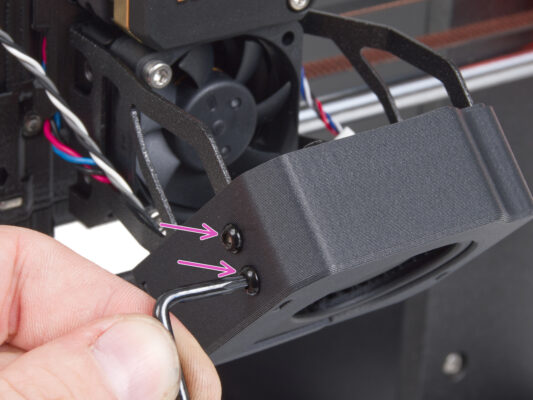
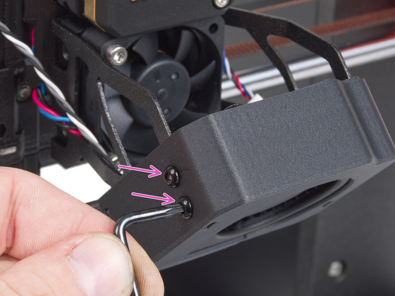
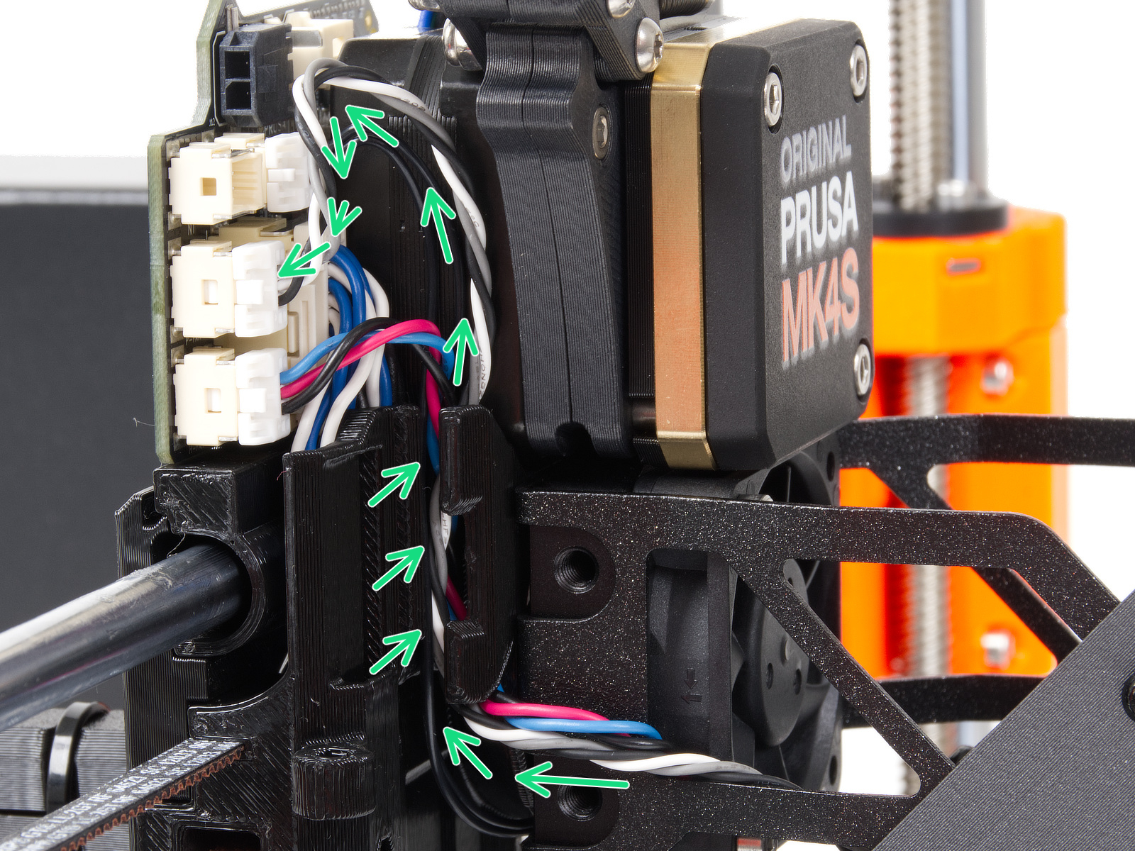
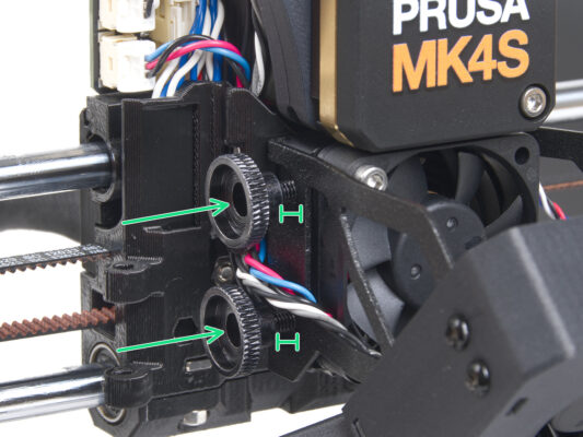
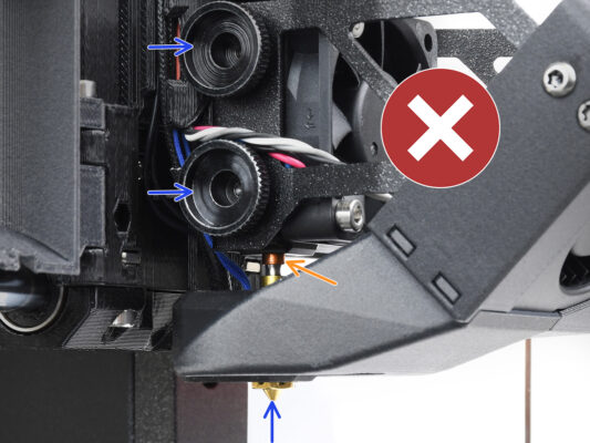
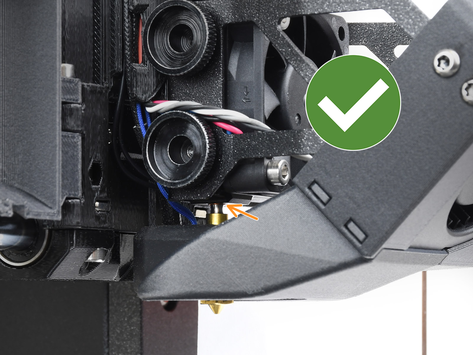
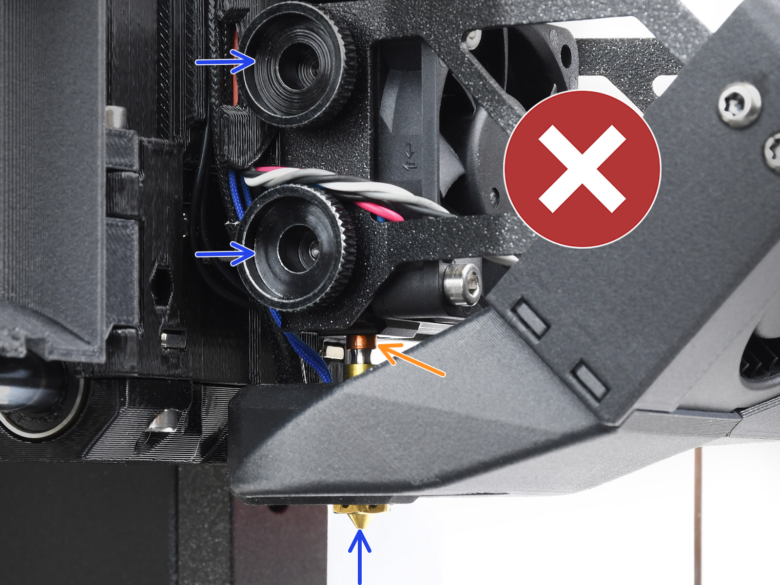
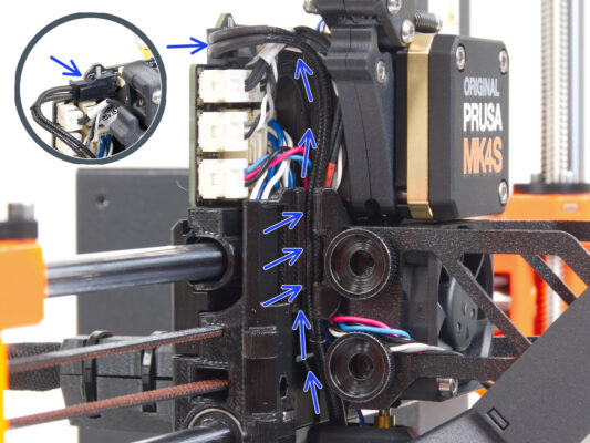
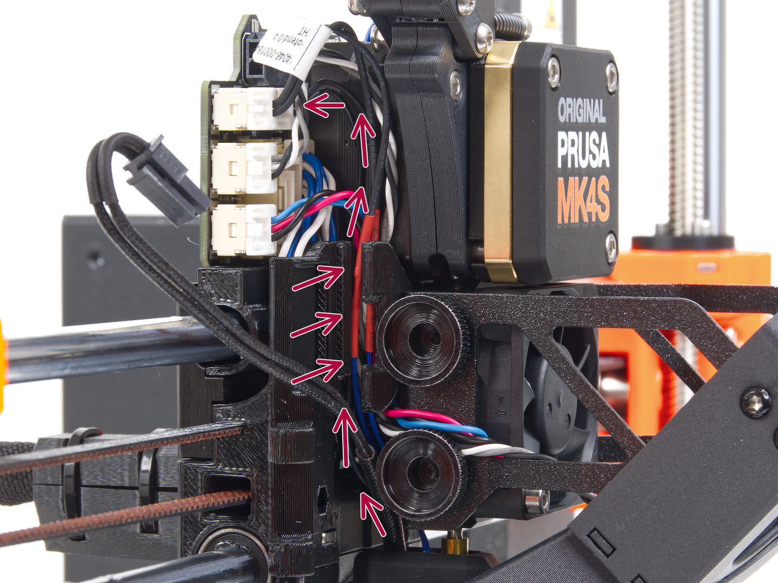
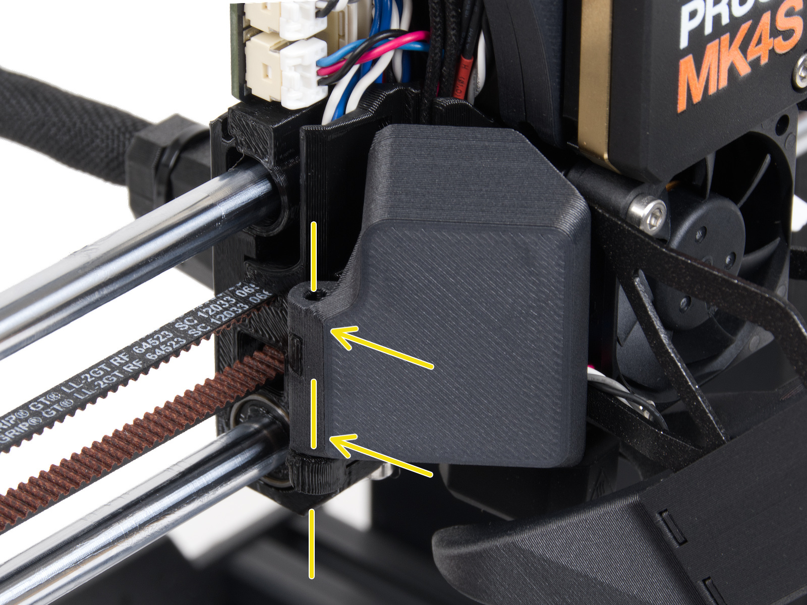
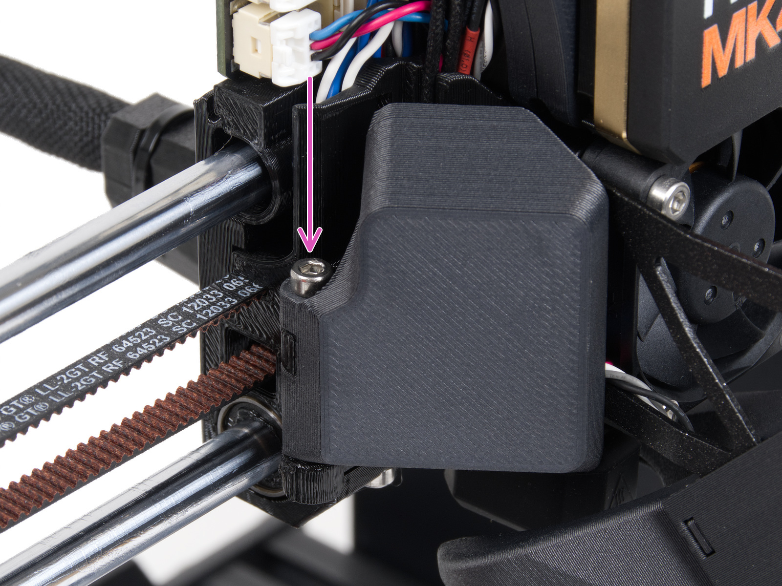
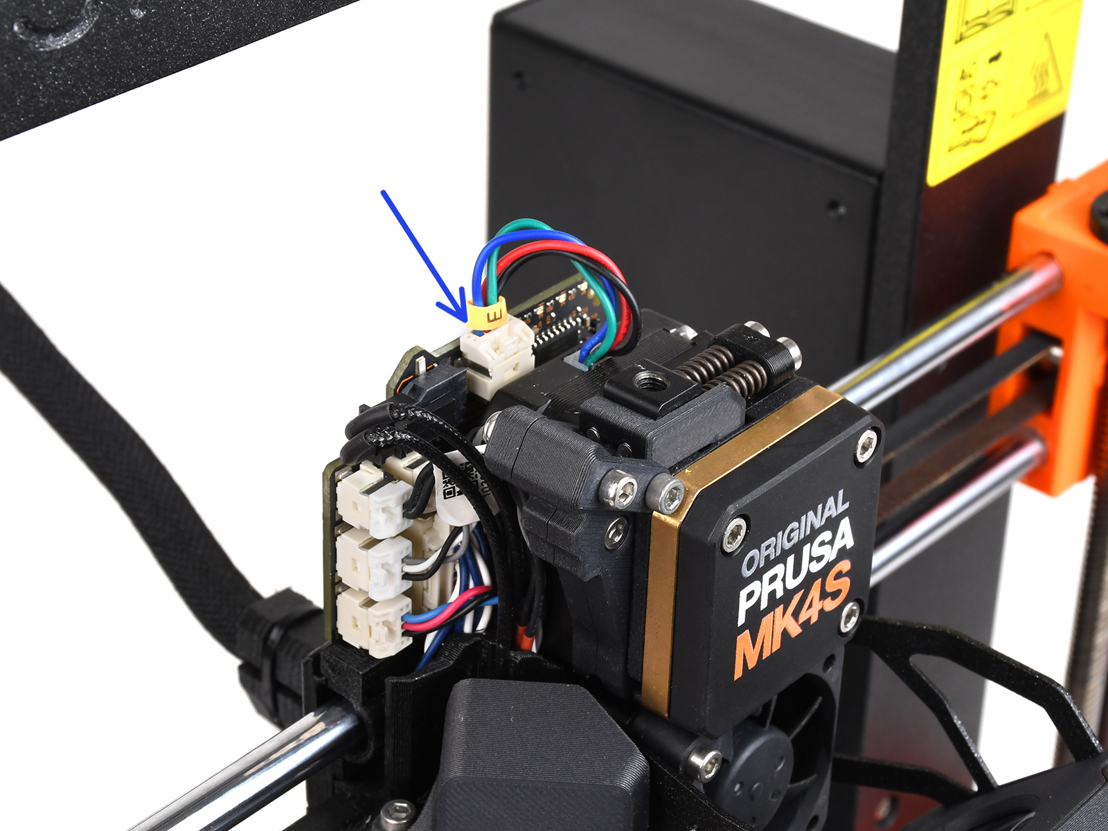
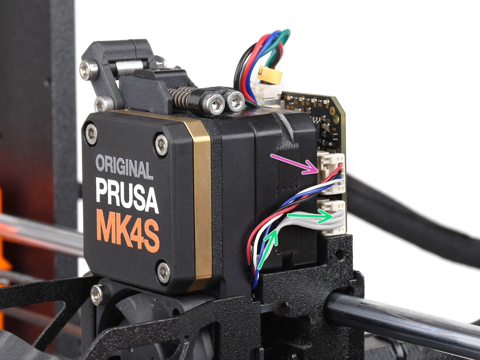
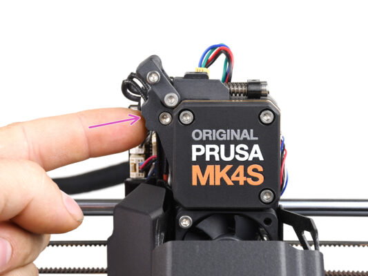
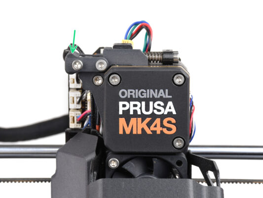
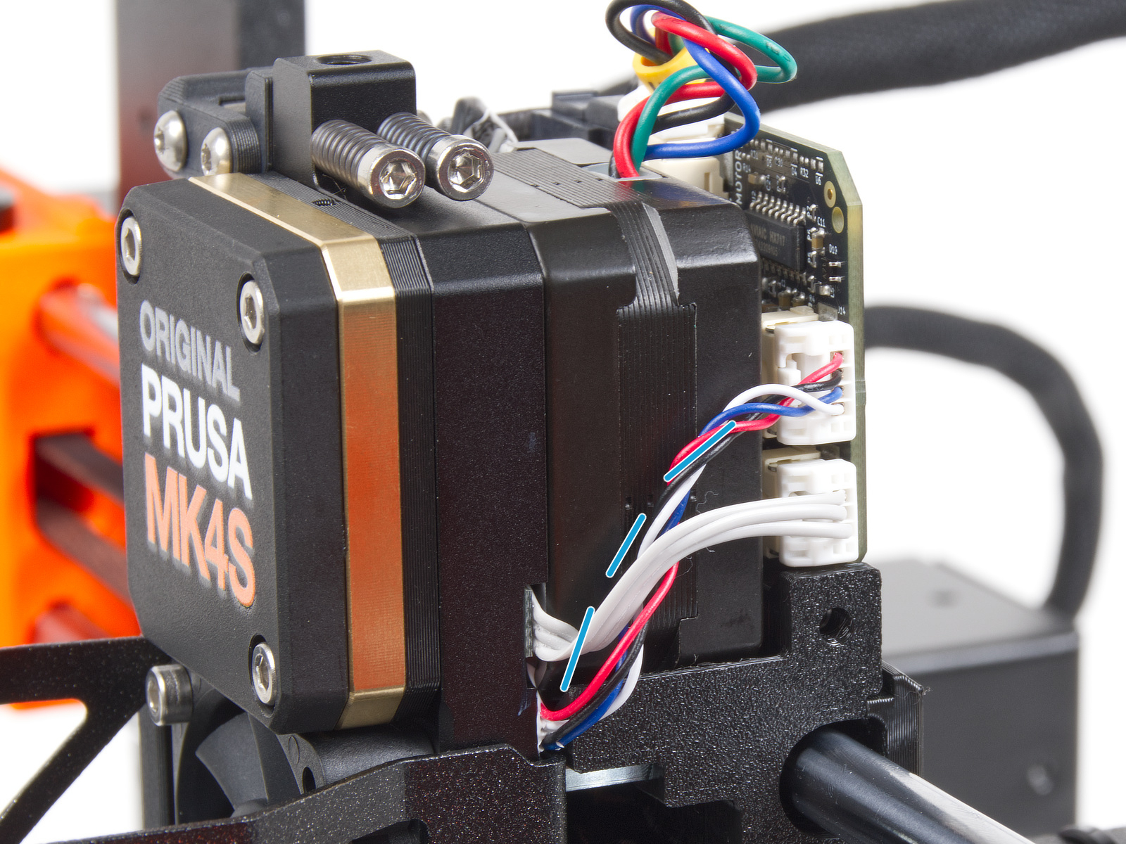
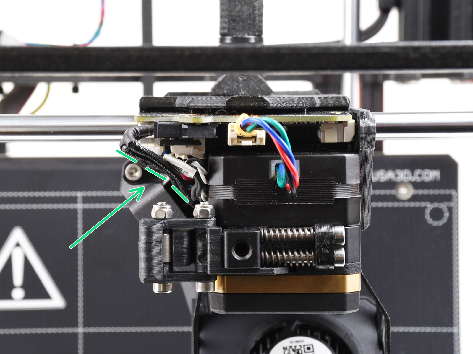
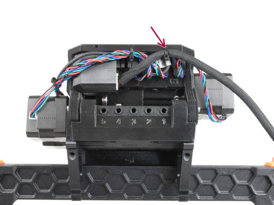
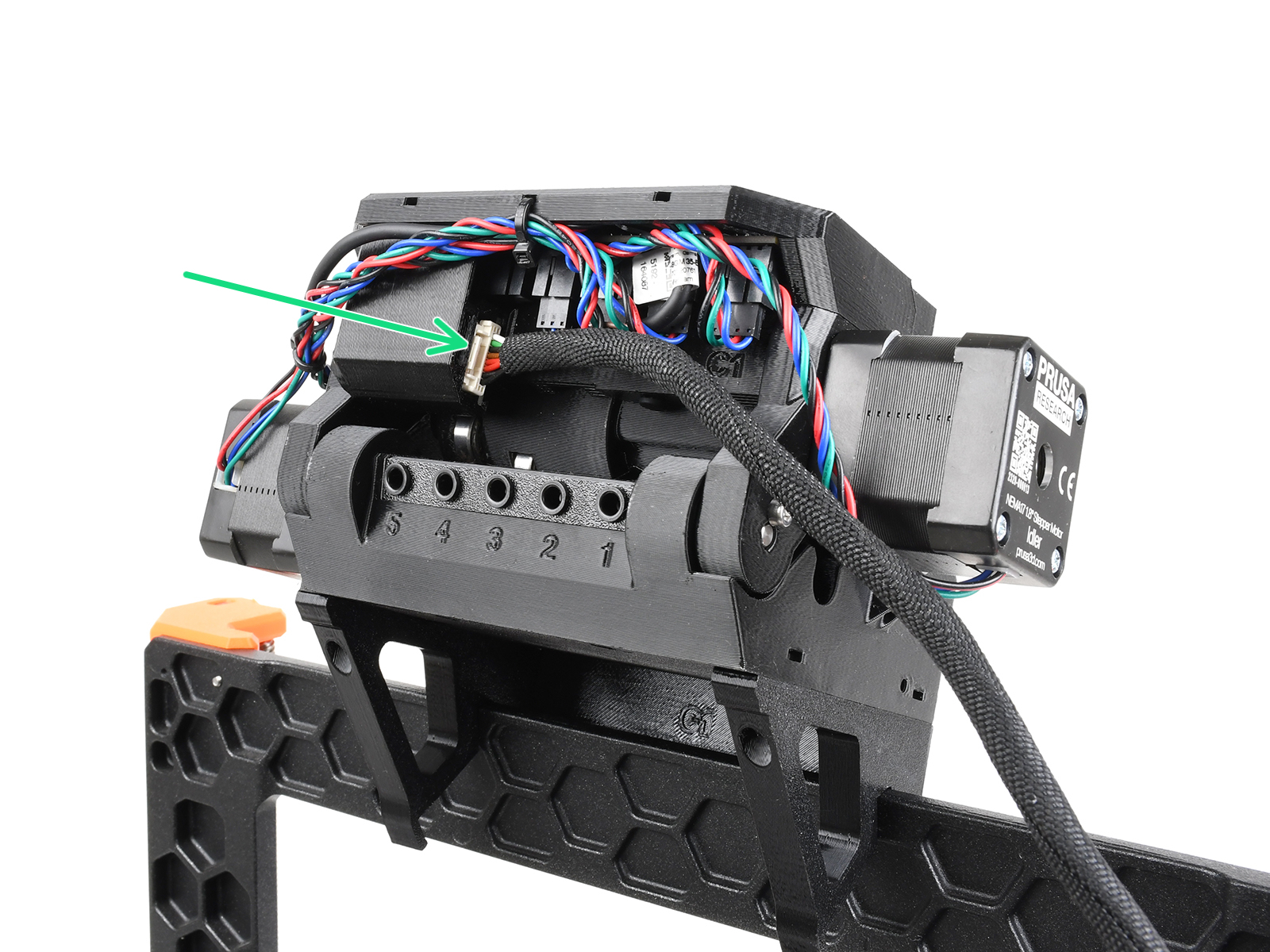
ケーブルを挟まないように注意してください!


If you have a question about something that isn't covered here, check out our additional resources.
And if that doesn't do the trick, you can send an inquiry to [email protected] or through the button below.

