NOTE: The following instructions are only for those who have purchased this optional add-on with the MINI Enclosure. If you have not purchased this add-on, please proceed to step Installing the top panel.
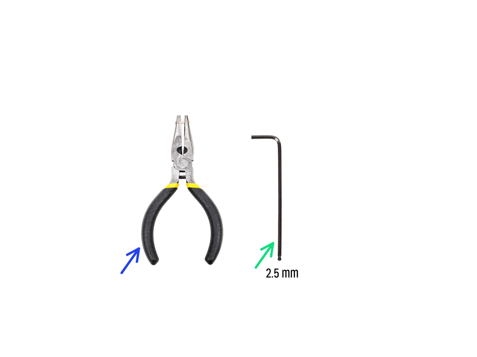
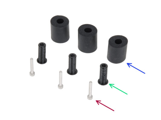
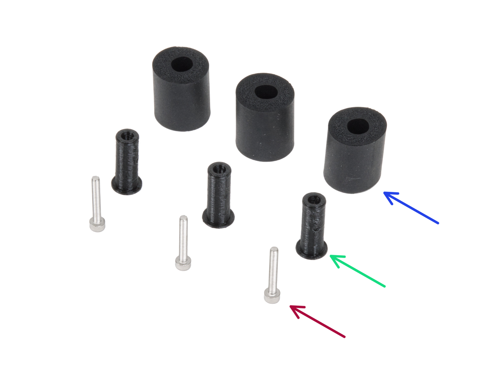
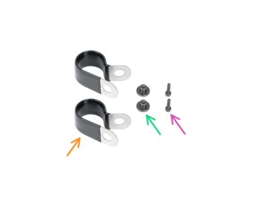
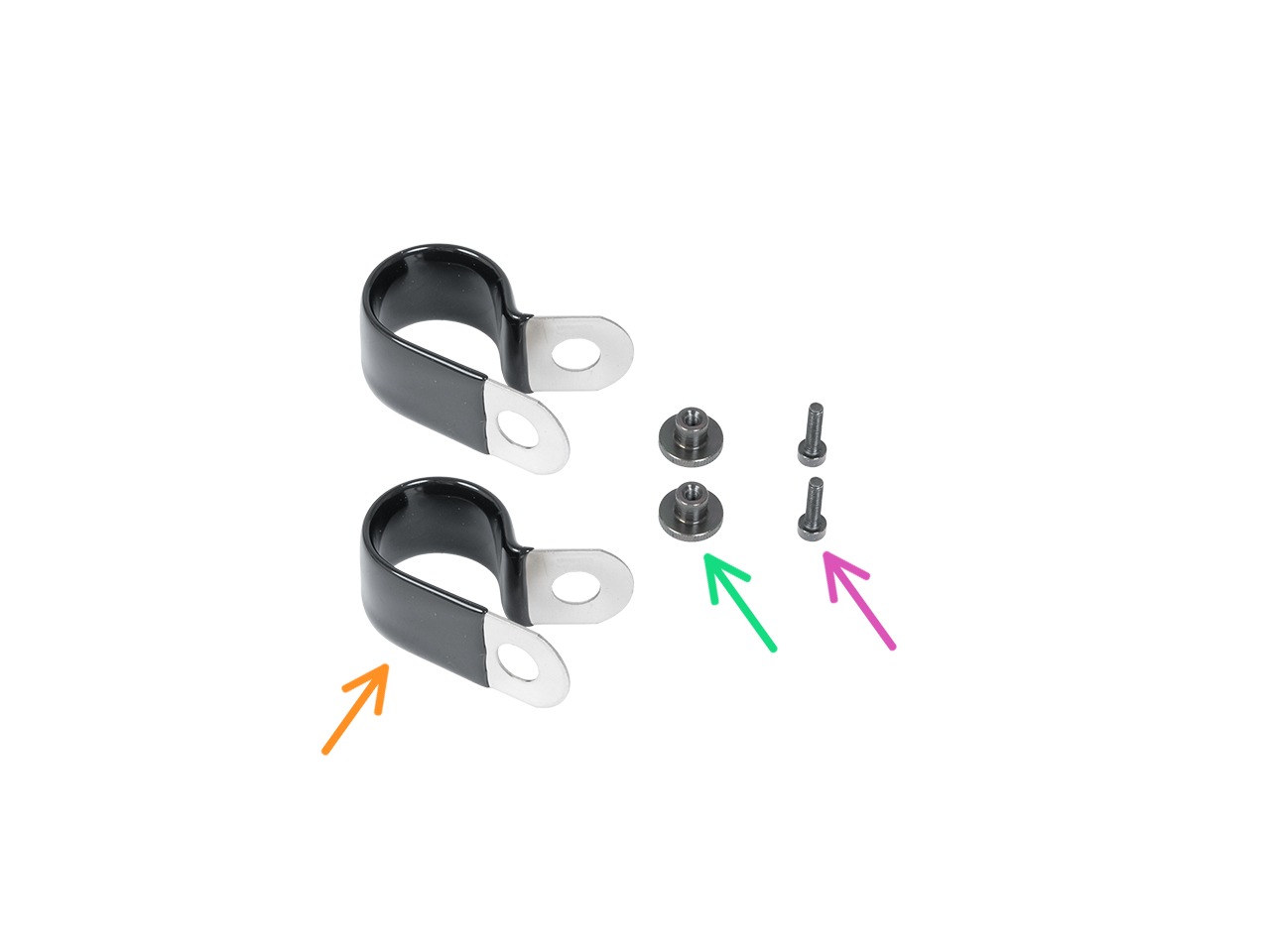
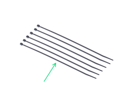
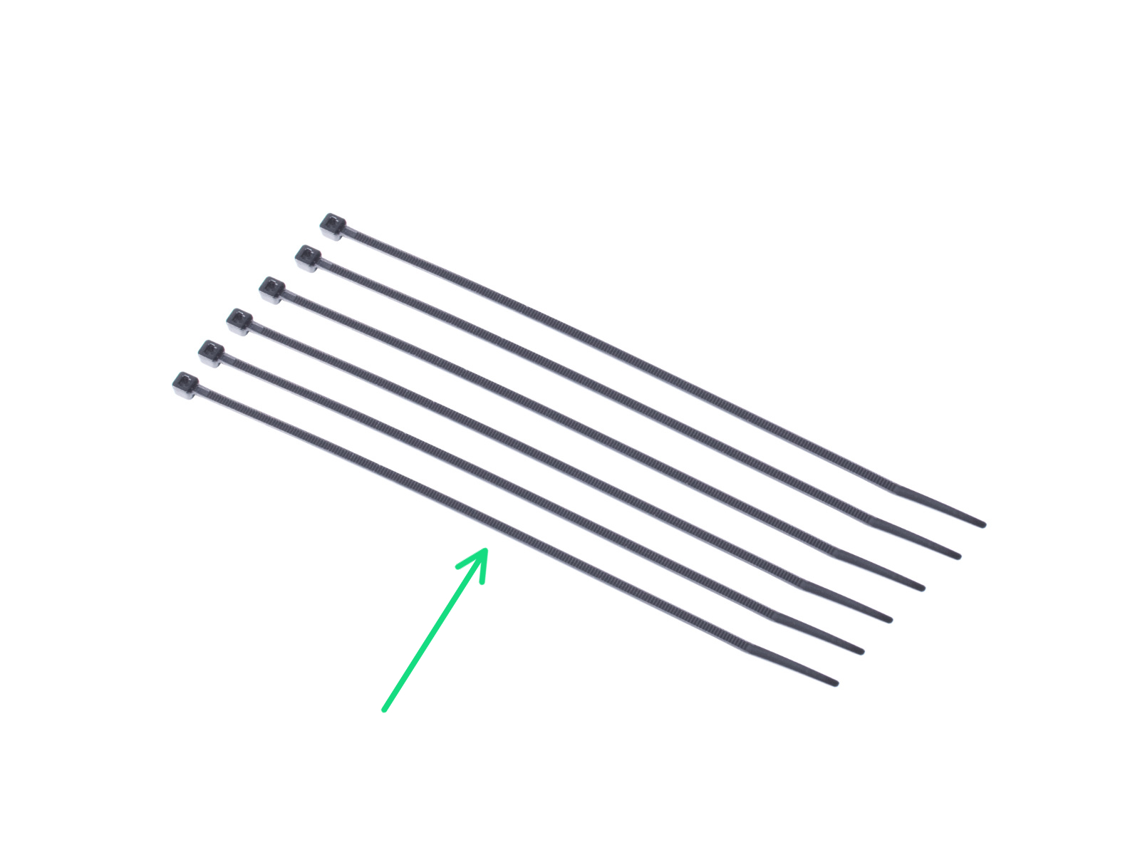
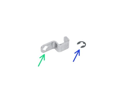
⬢Pour les étapes suivantes, merci de préparer :
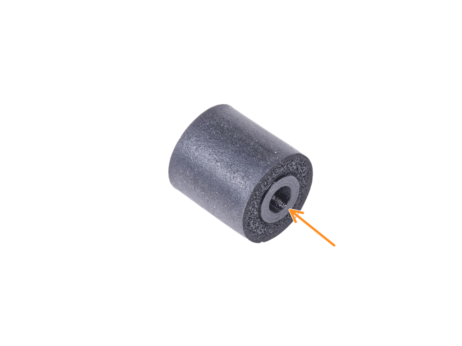
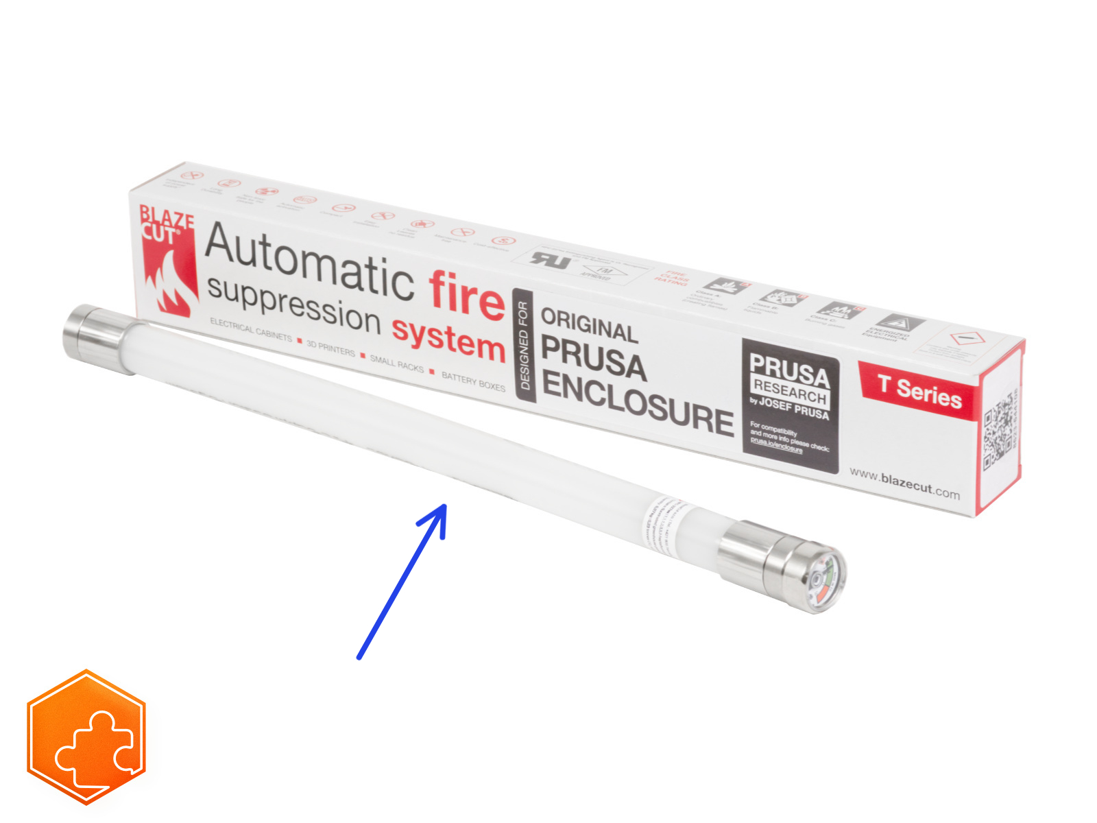
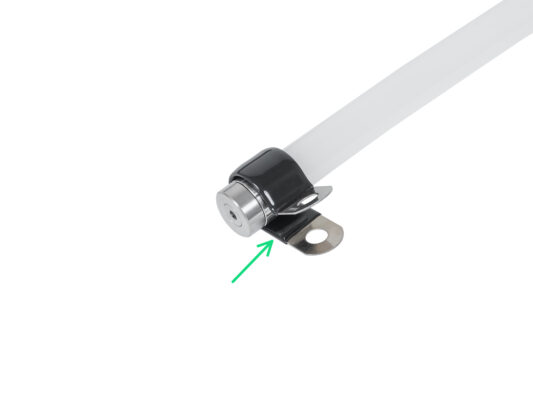
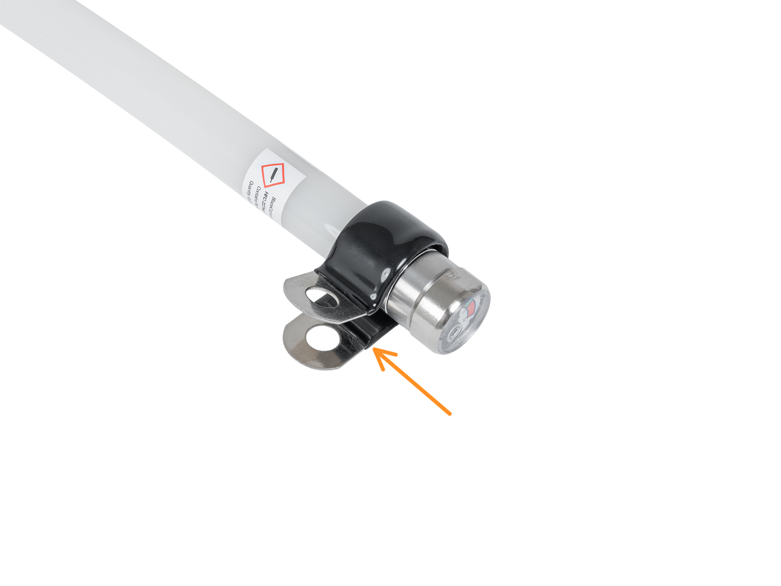
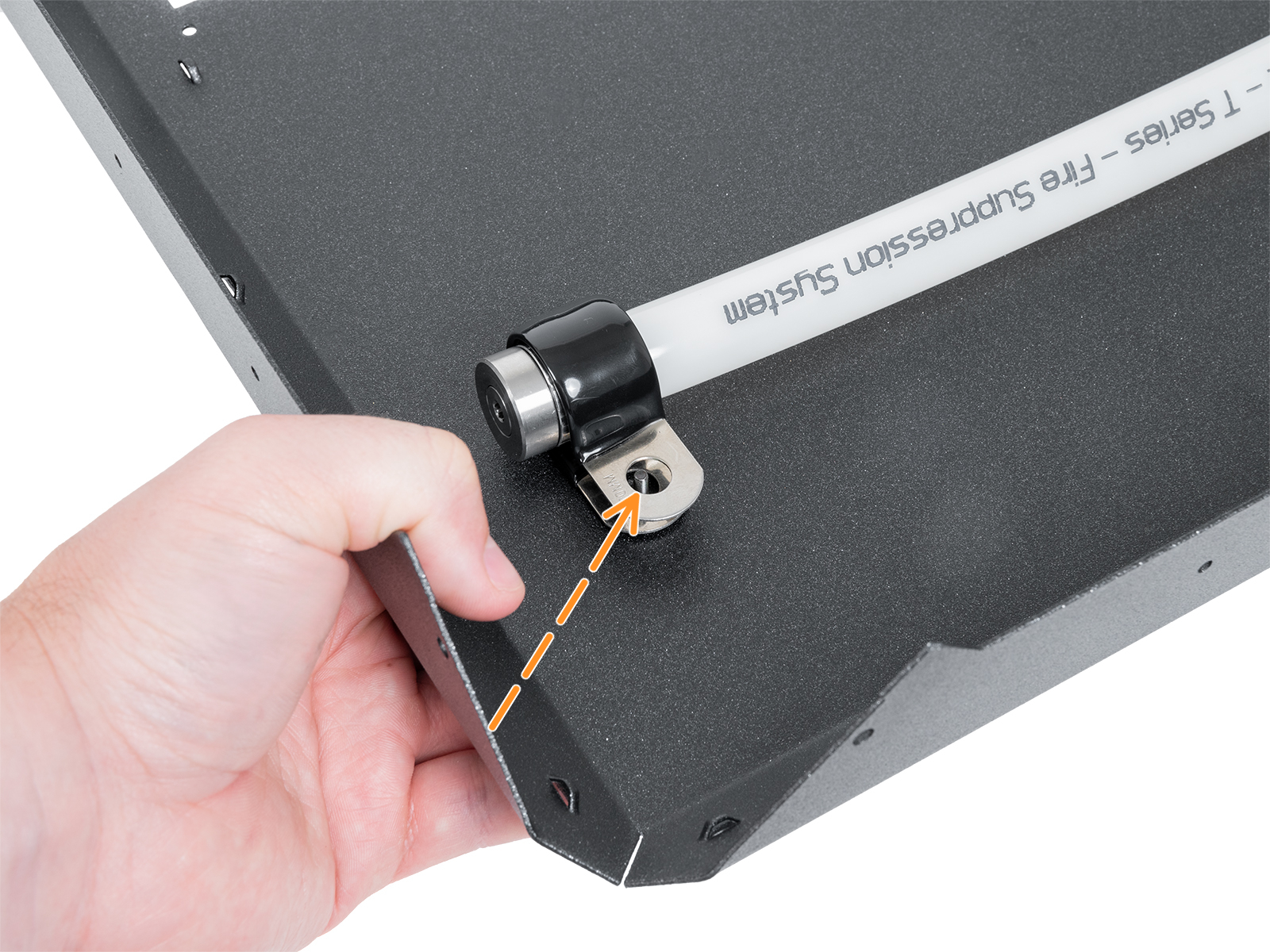
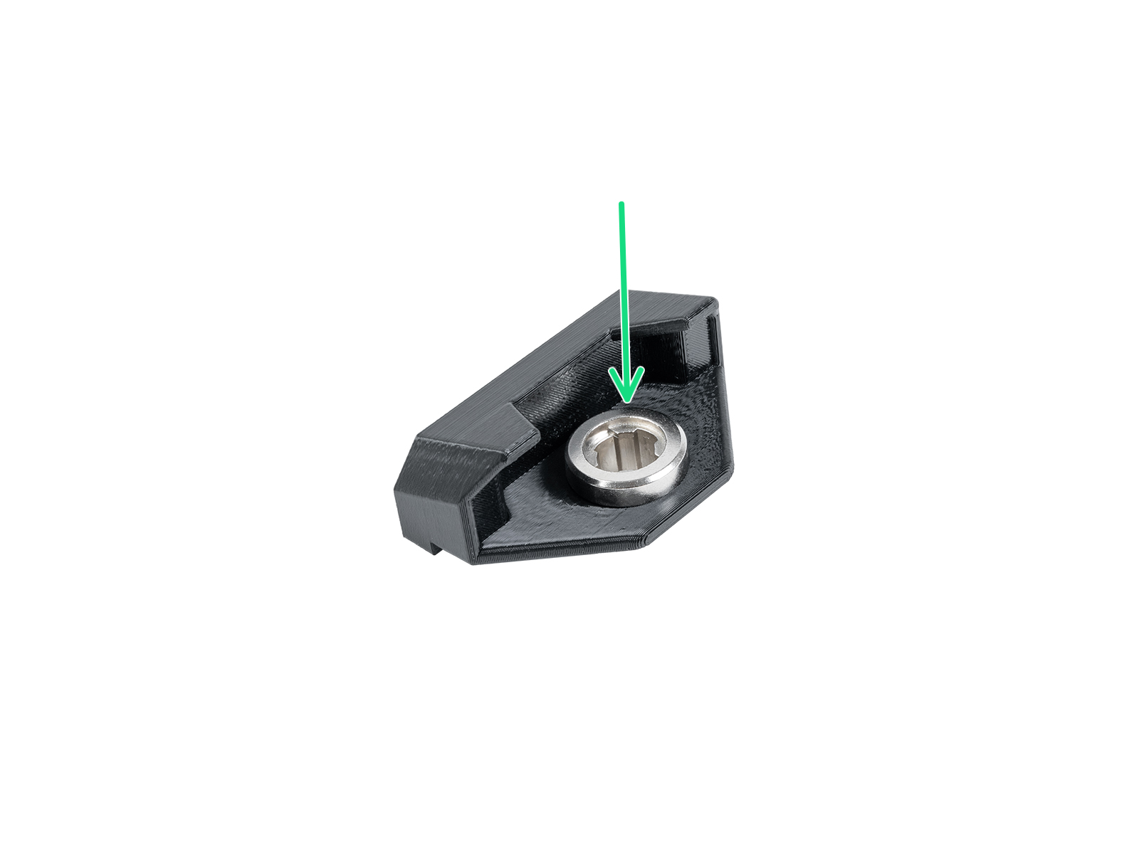
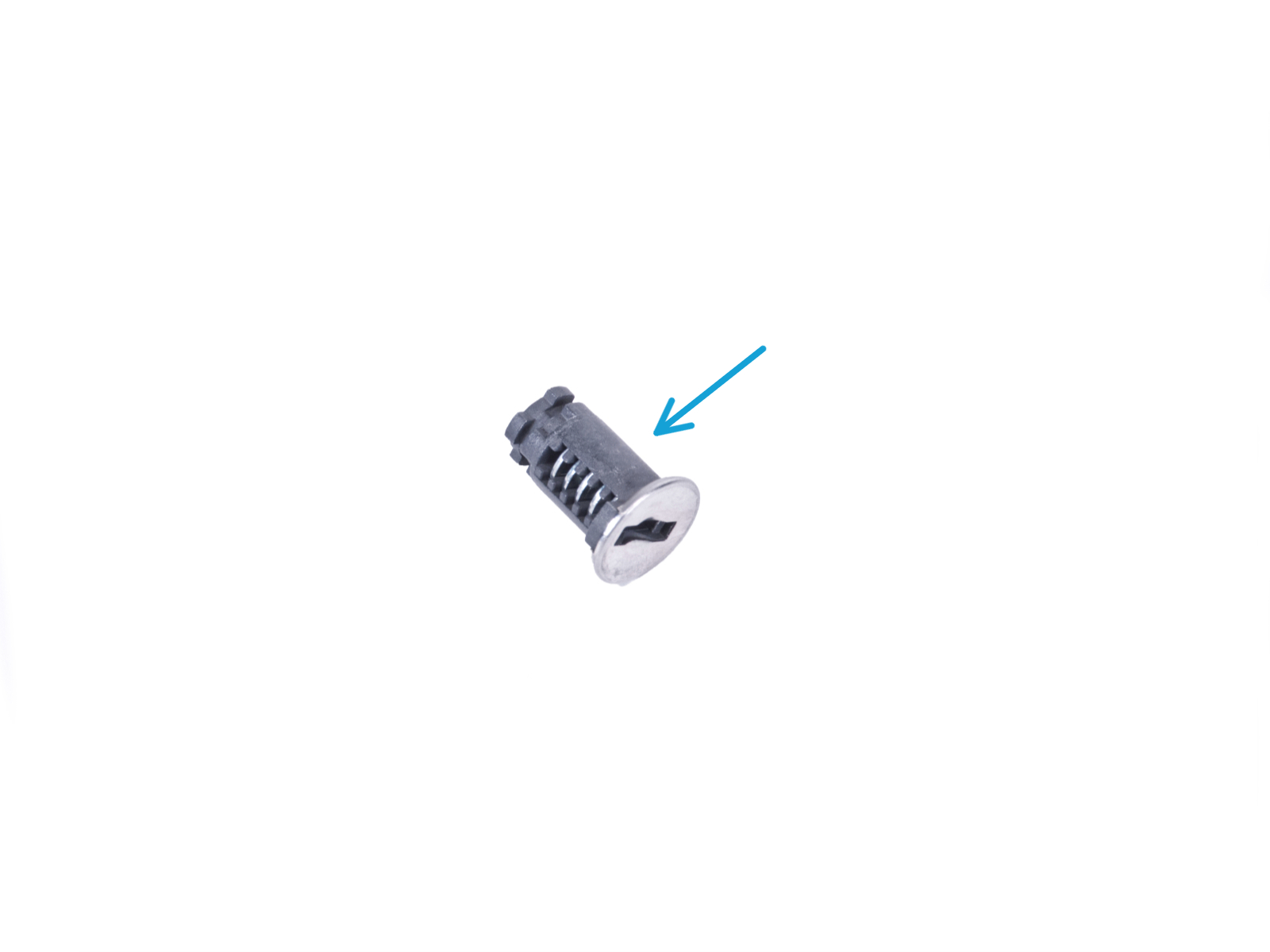
⬢Tube du système d'extinction d'incendie (1x) type : Système d'extinction d'incendie série T033E BlazeCut T Series avec manomètre
Manipulez le tube avec précaution pour éviter de l'endommager.
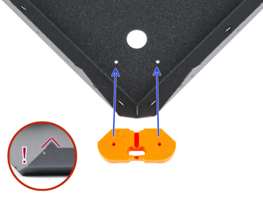
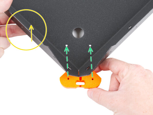
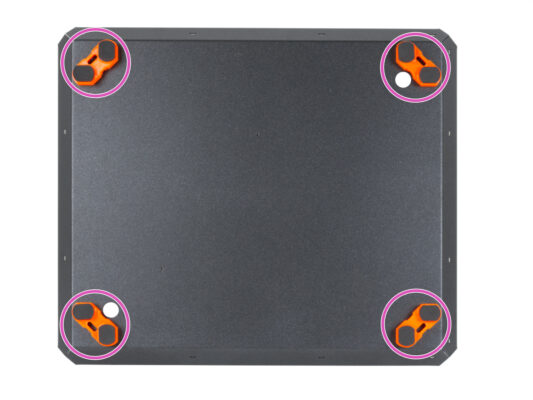
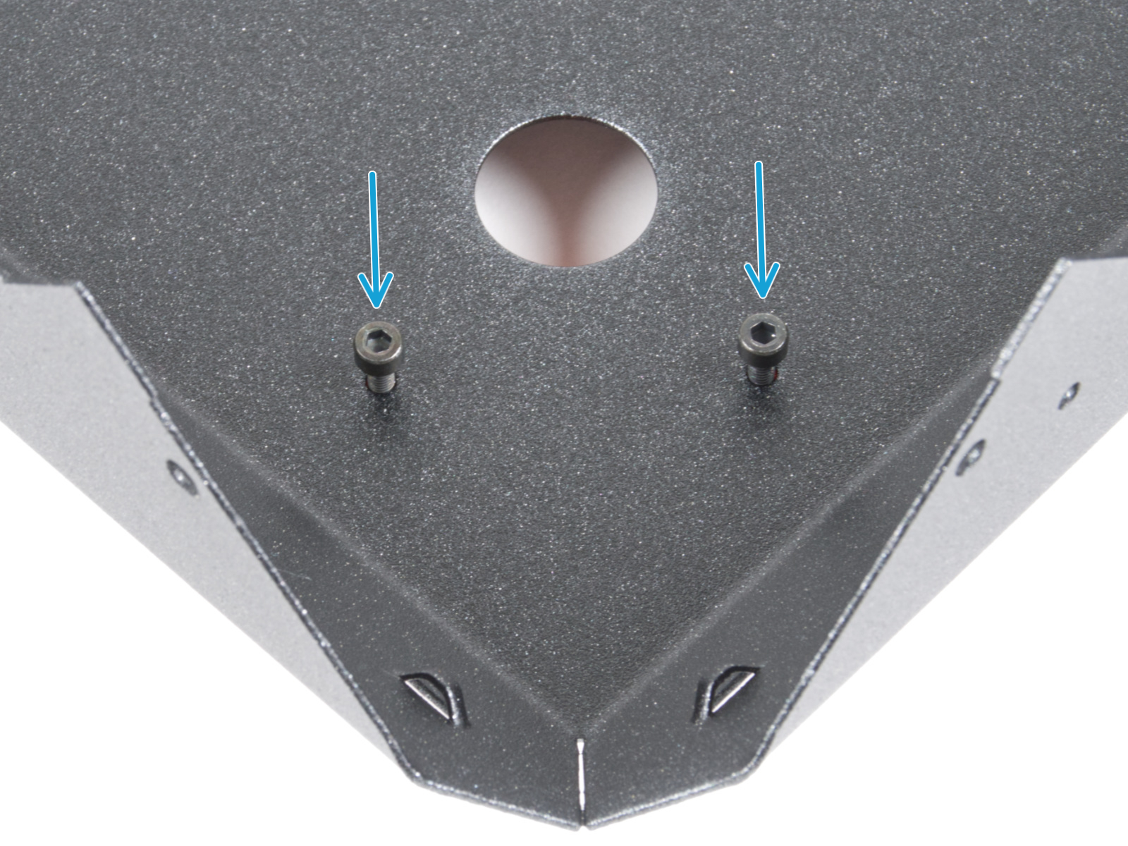
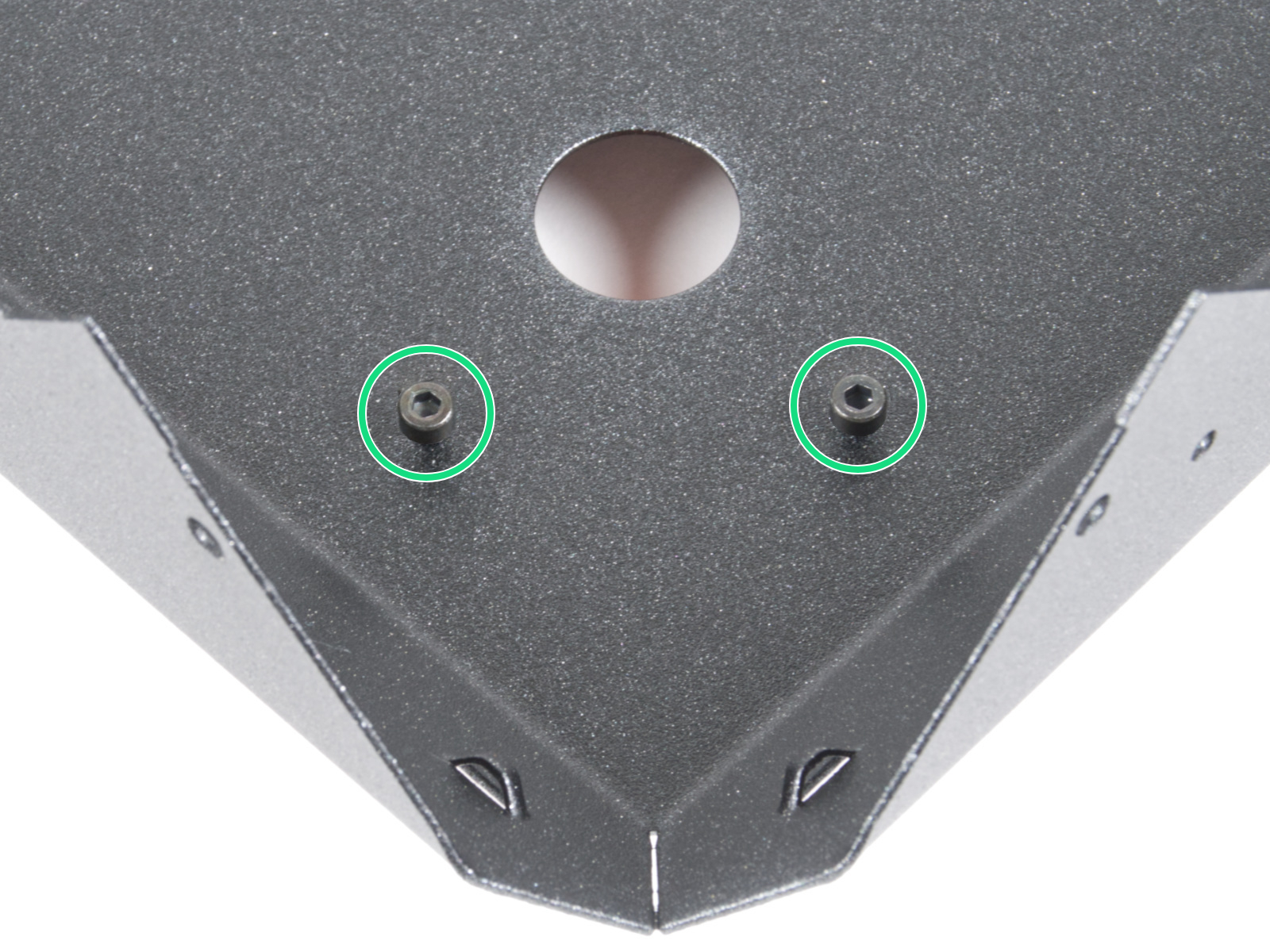
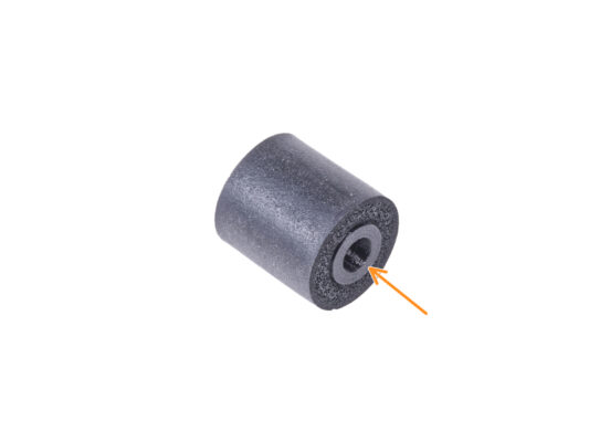
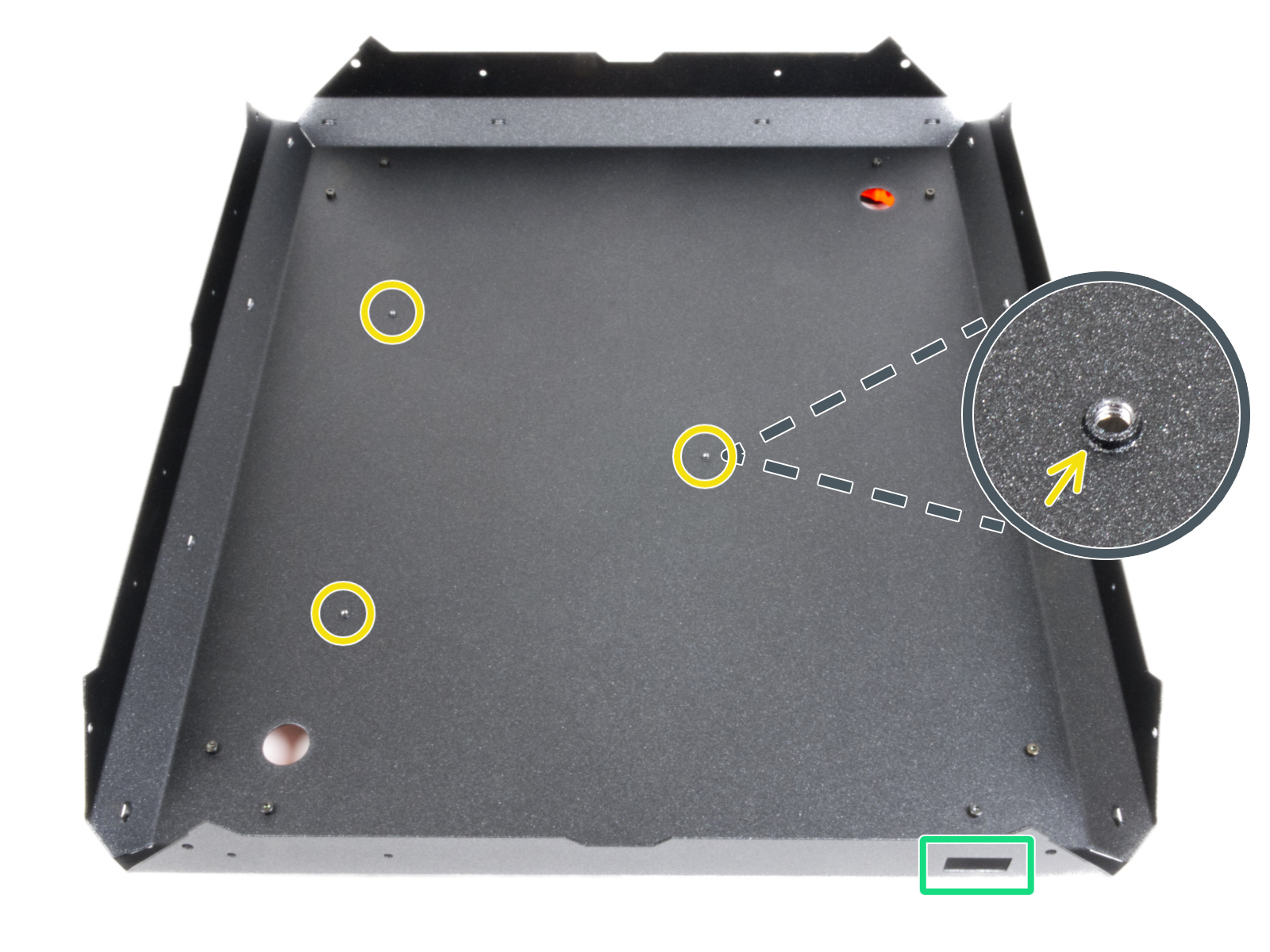
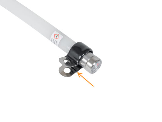
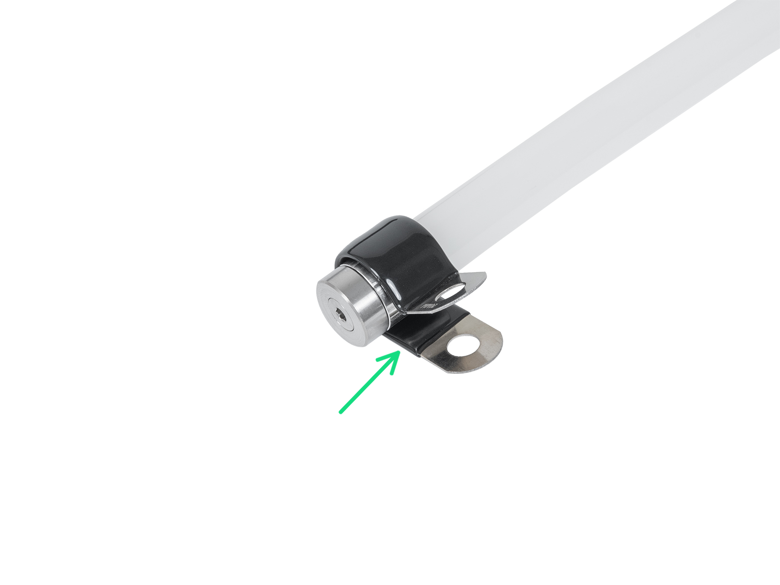
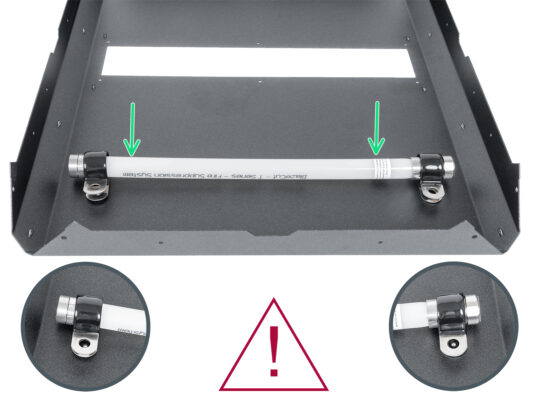
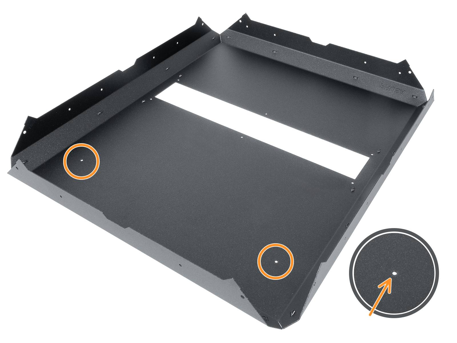
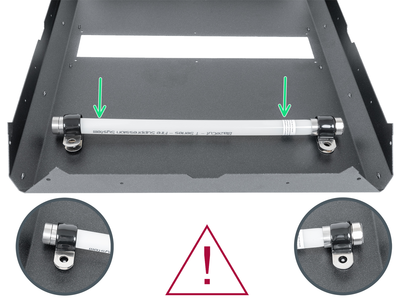
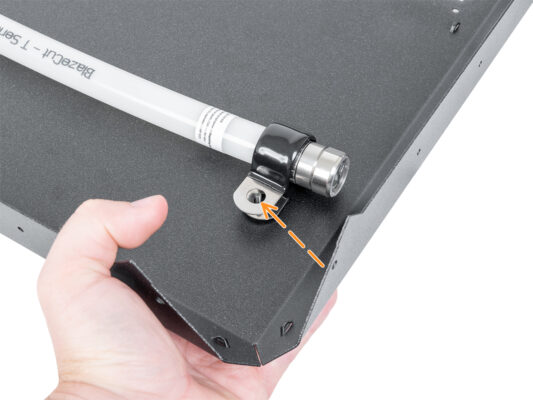
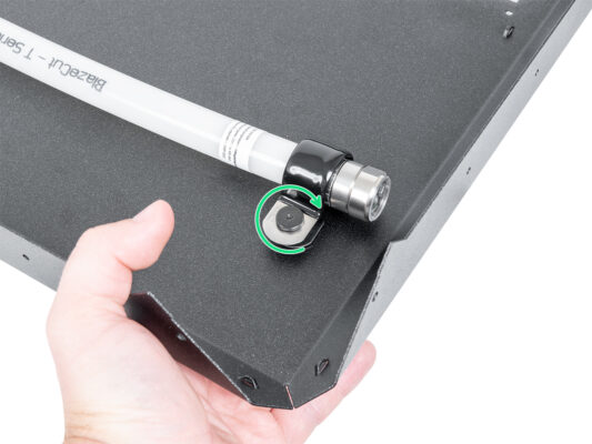
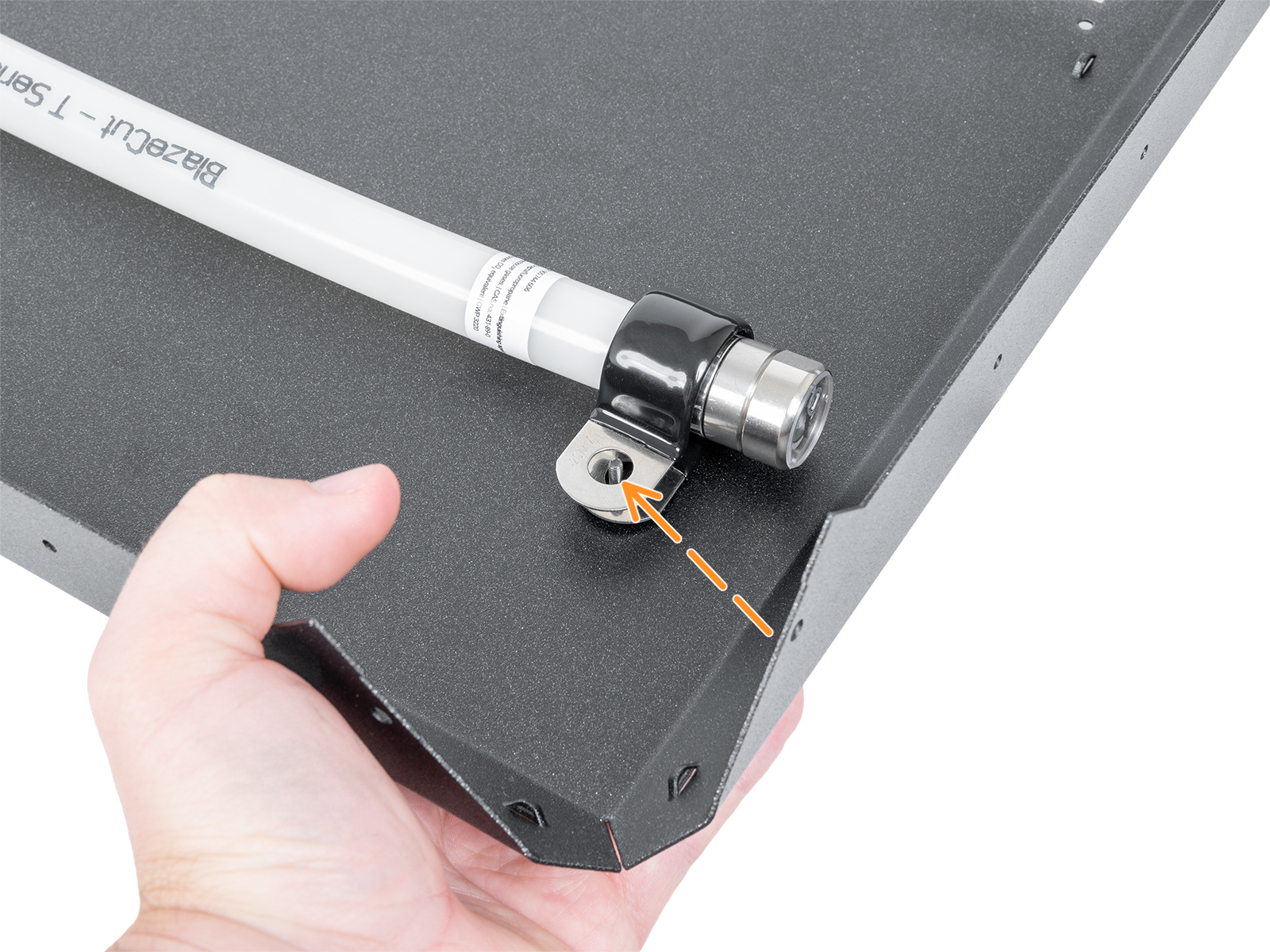
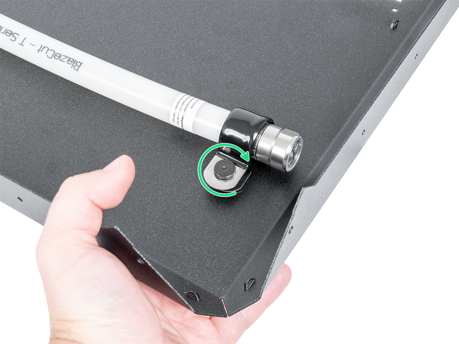
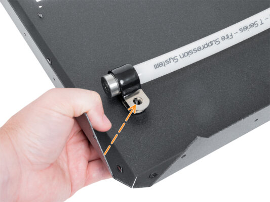
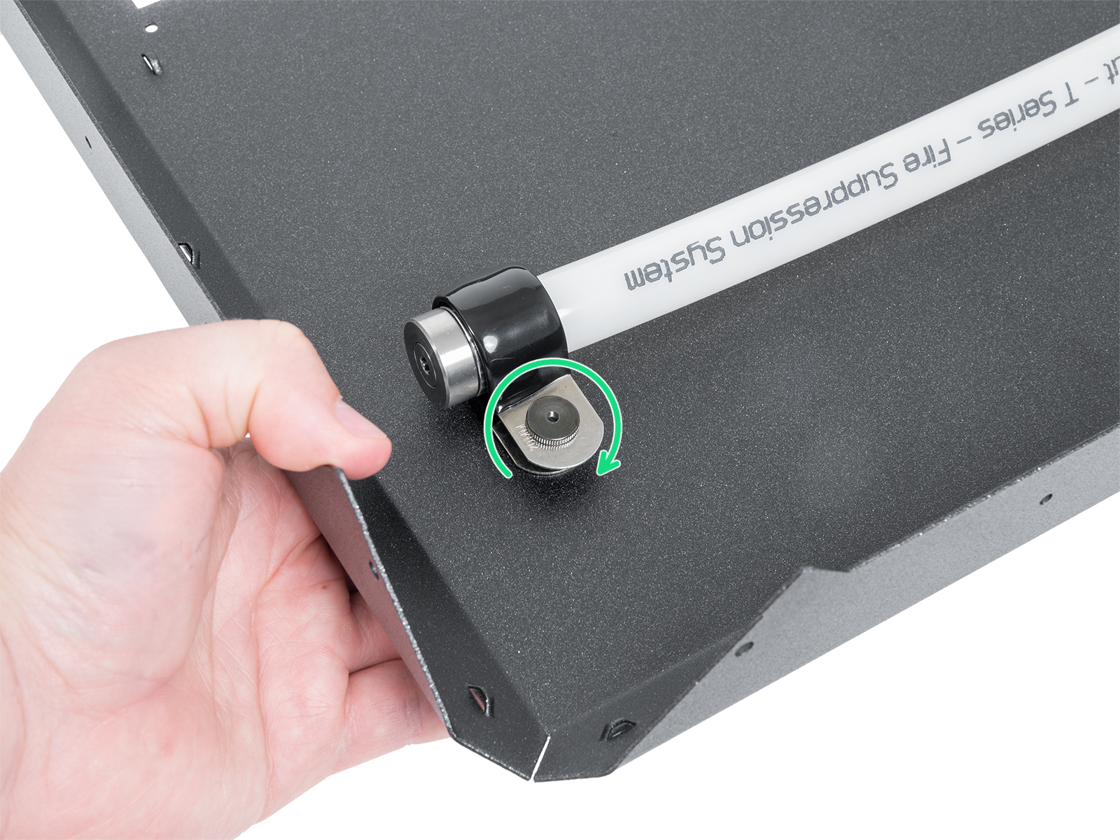
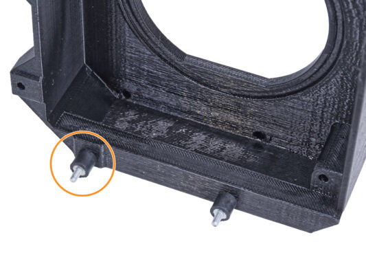
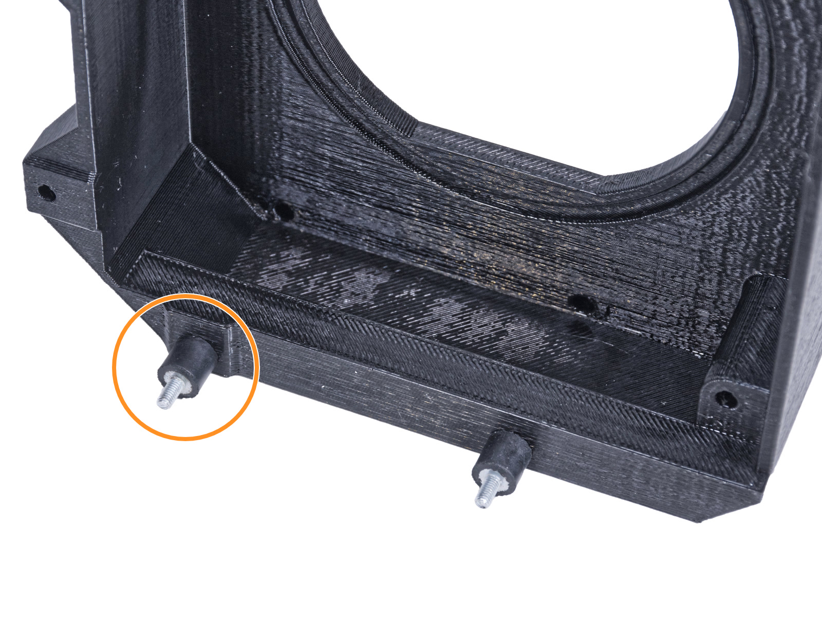
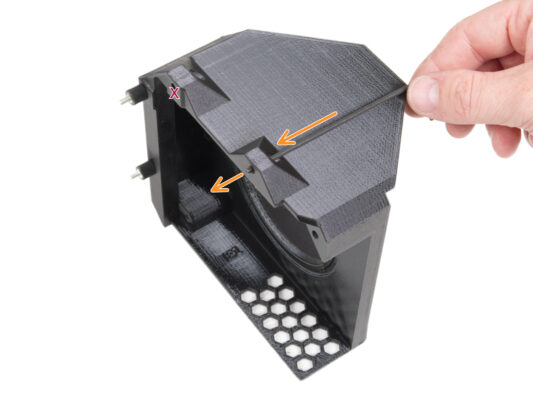
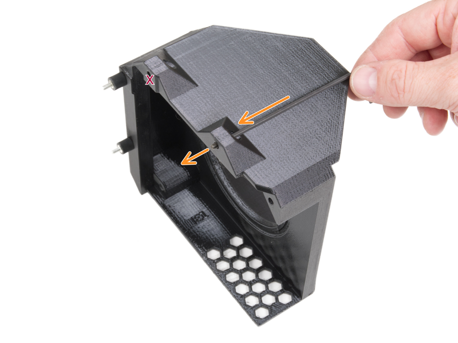
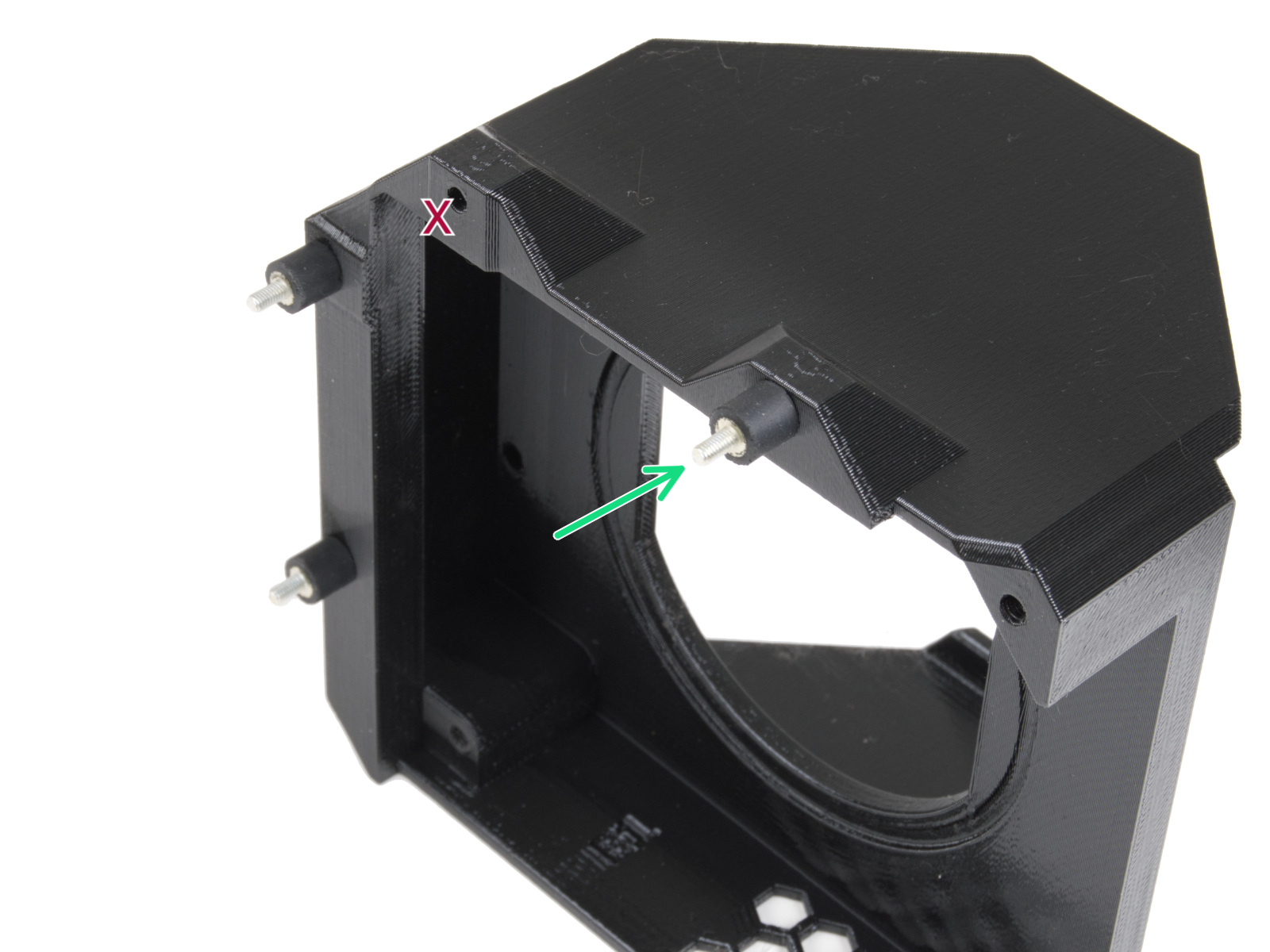
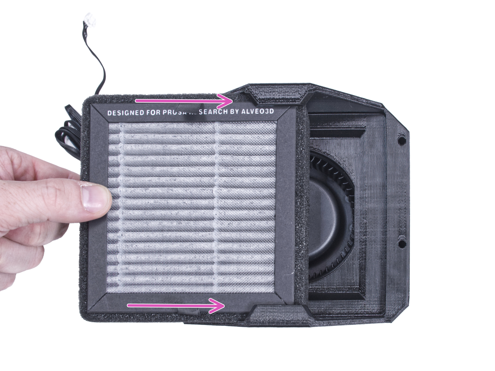
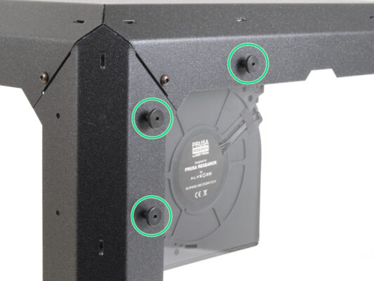
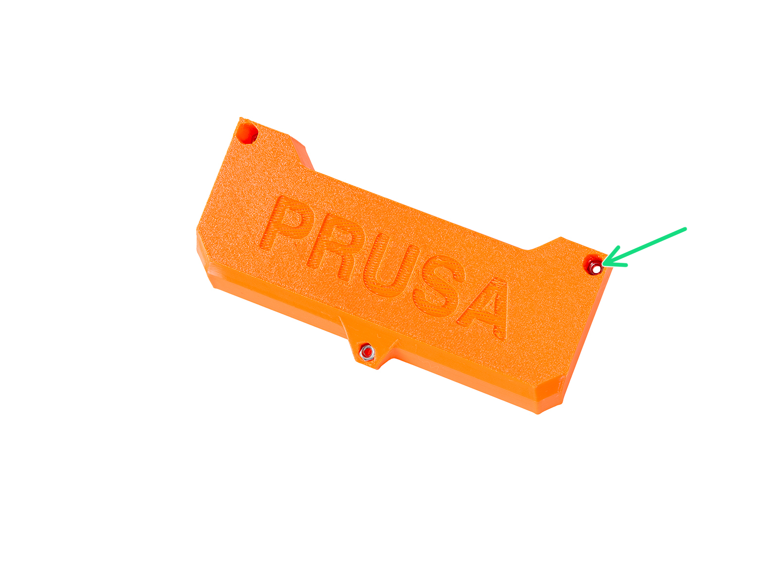
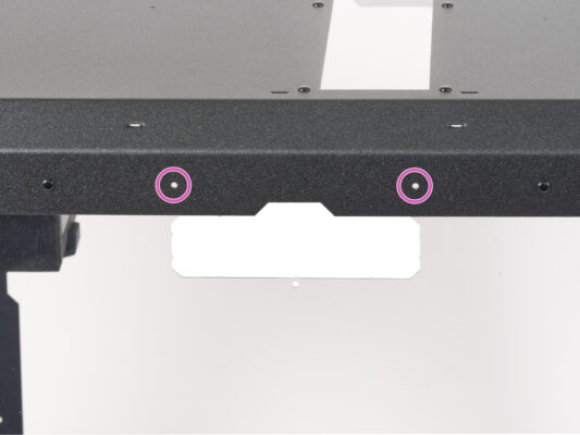
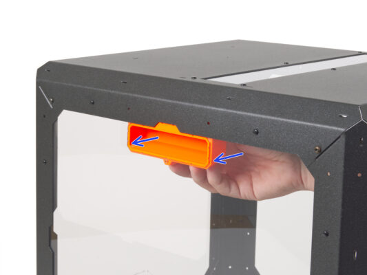
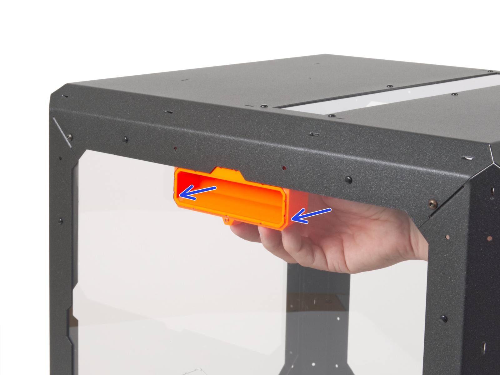
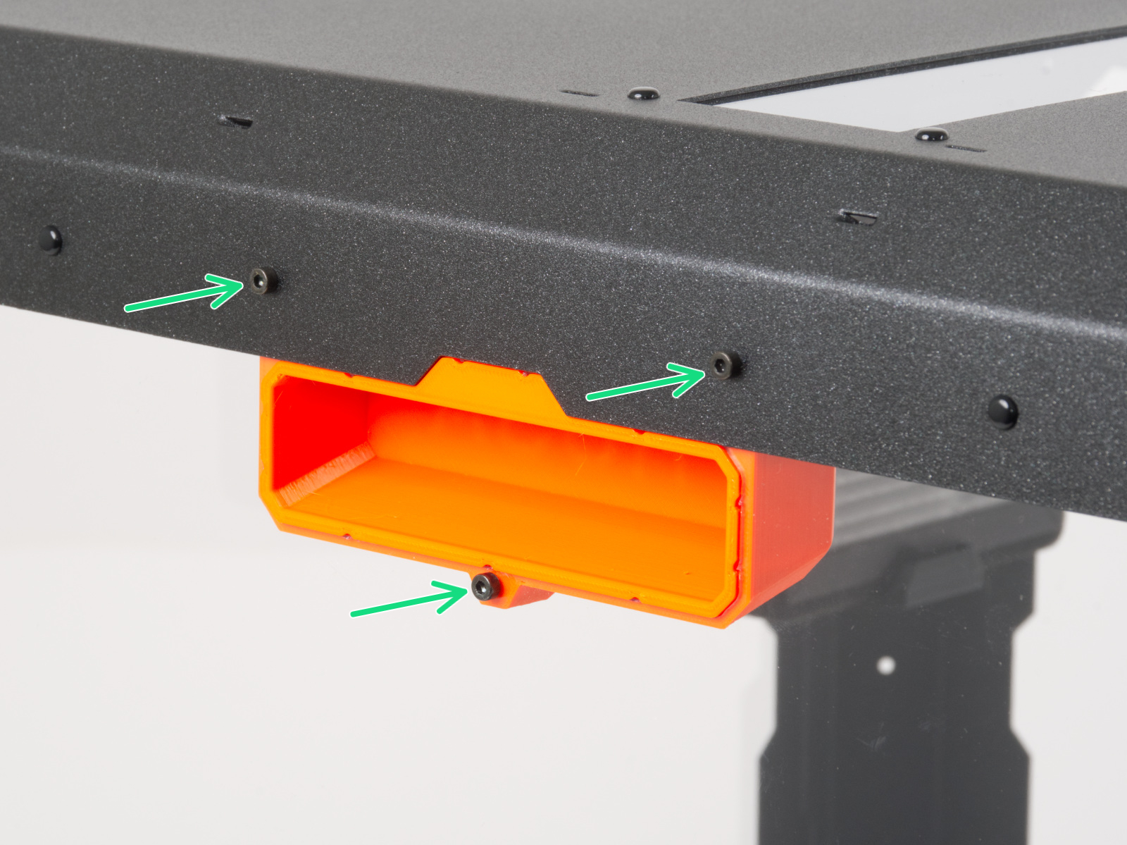
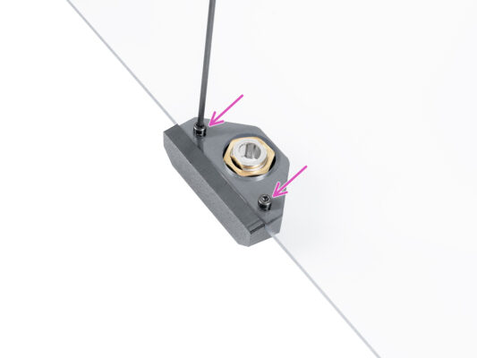
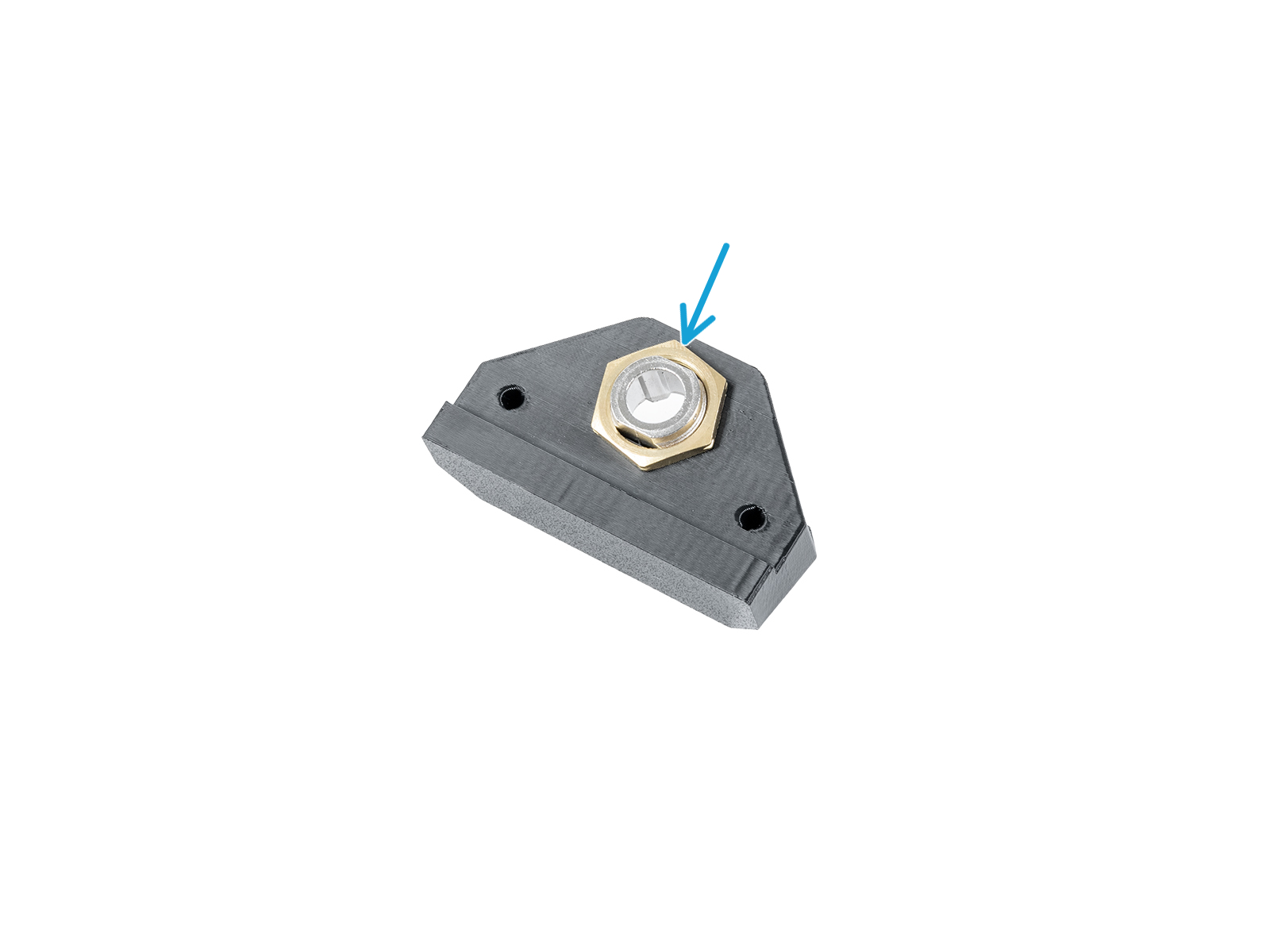
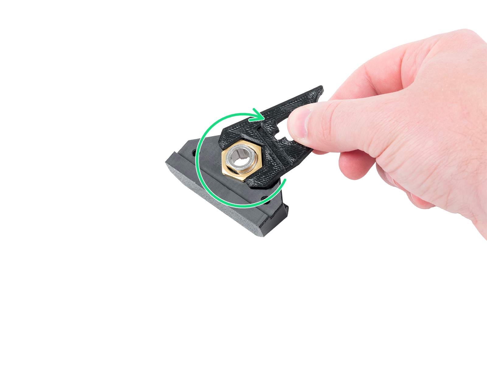
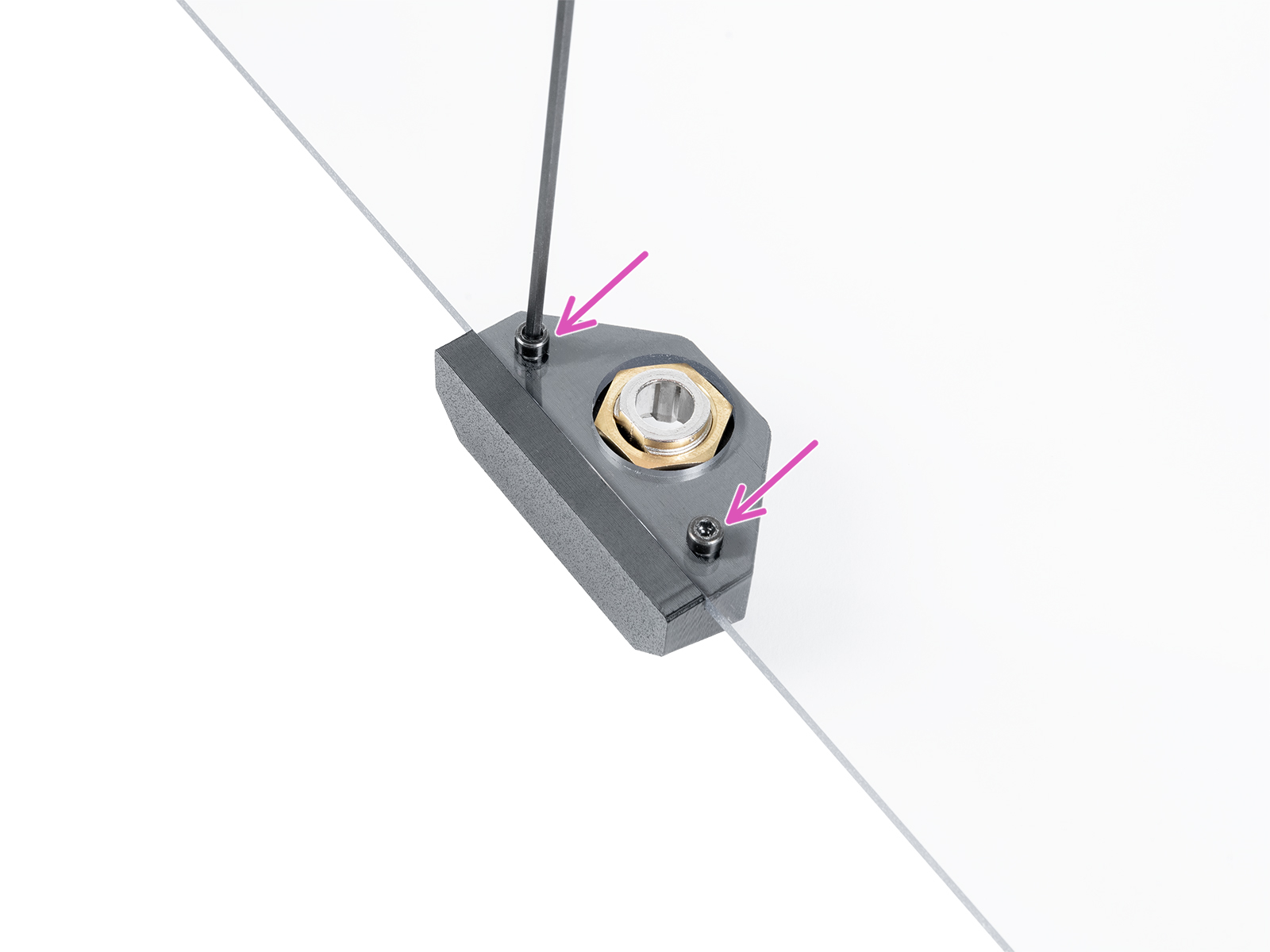
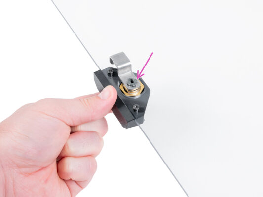
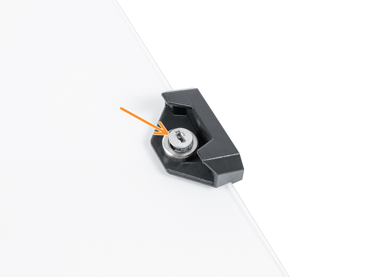
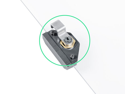
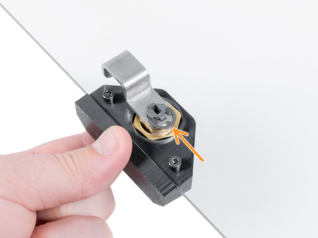
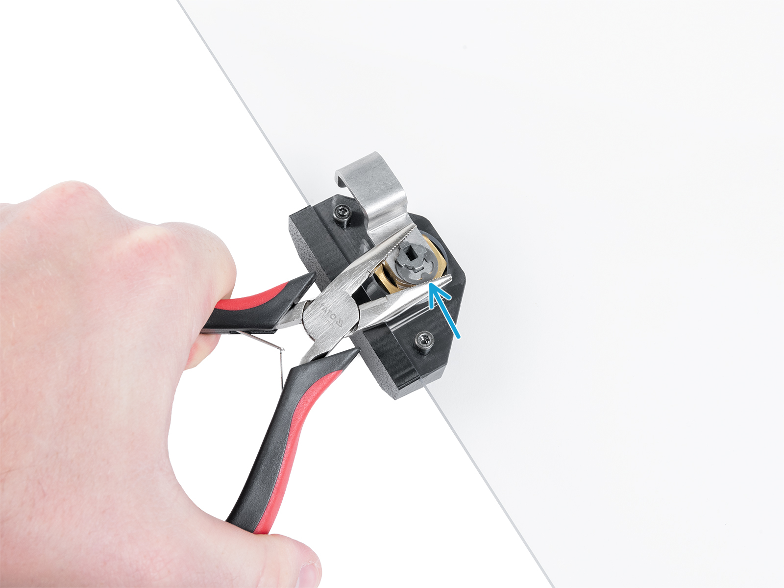
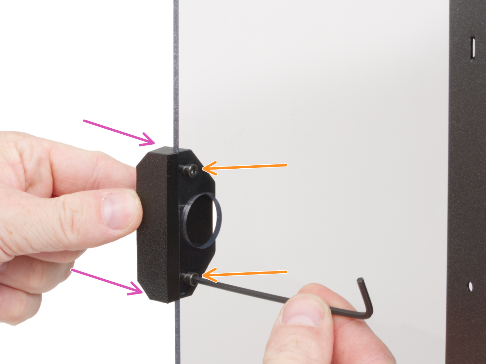
⬢Attach the prepared Fire suppression and align the bracket with the holes in the MINI Top panel. Mind the orientation of the Fire suppression in the picture.
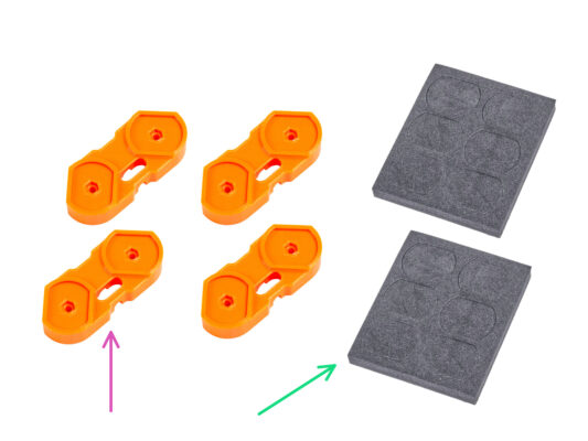
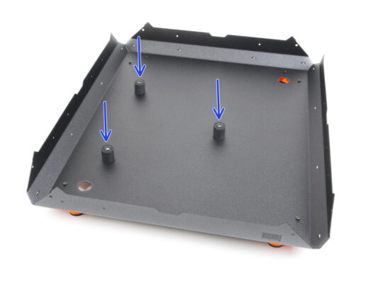
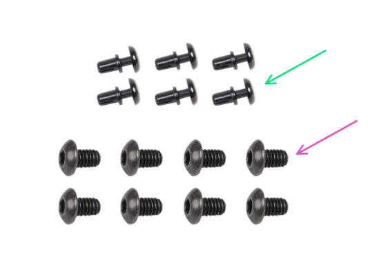
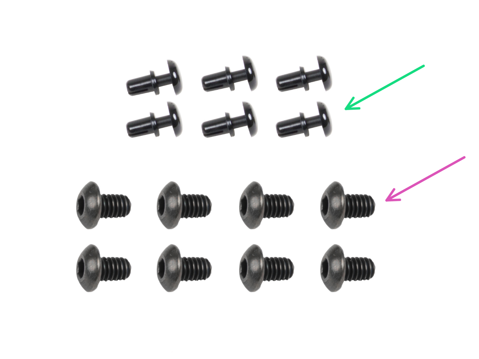
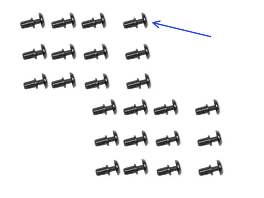
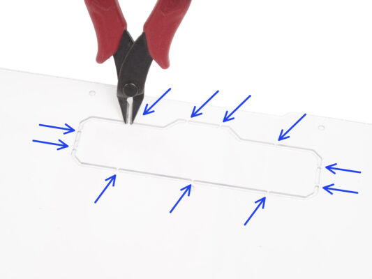
In this step, you will learn how to secure the panels with the nylon rivets. Remember this method, as you will use it throughout the assembly.
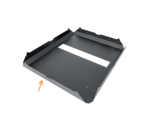
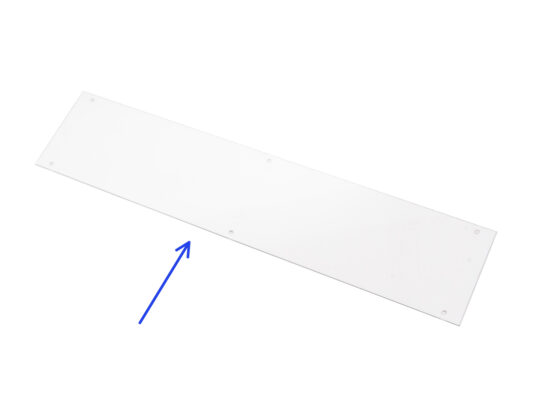
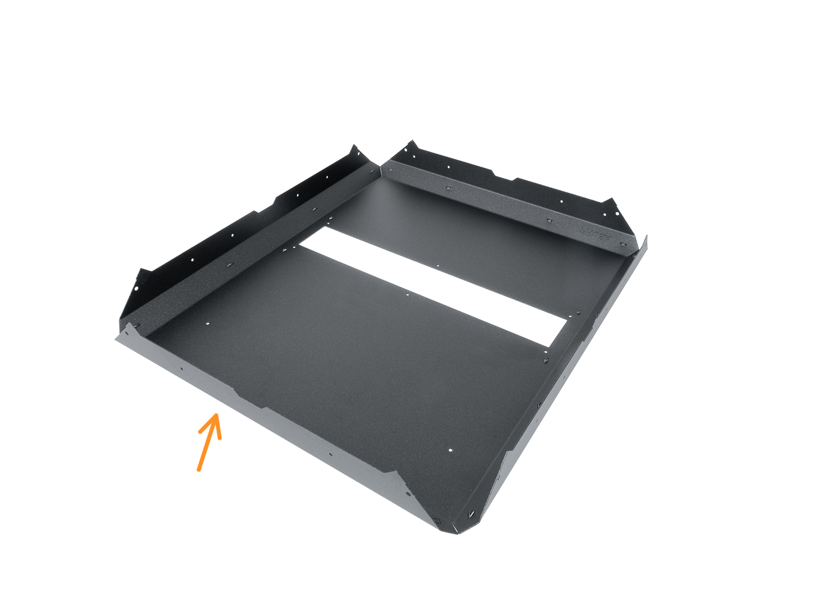
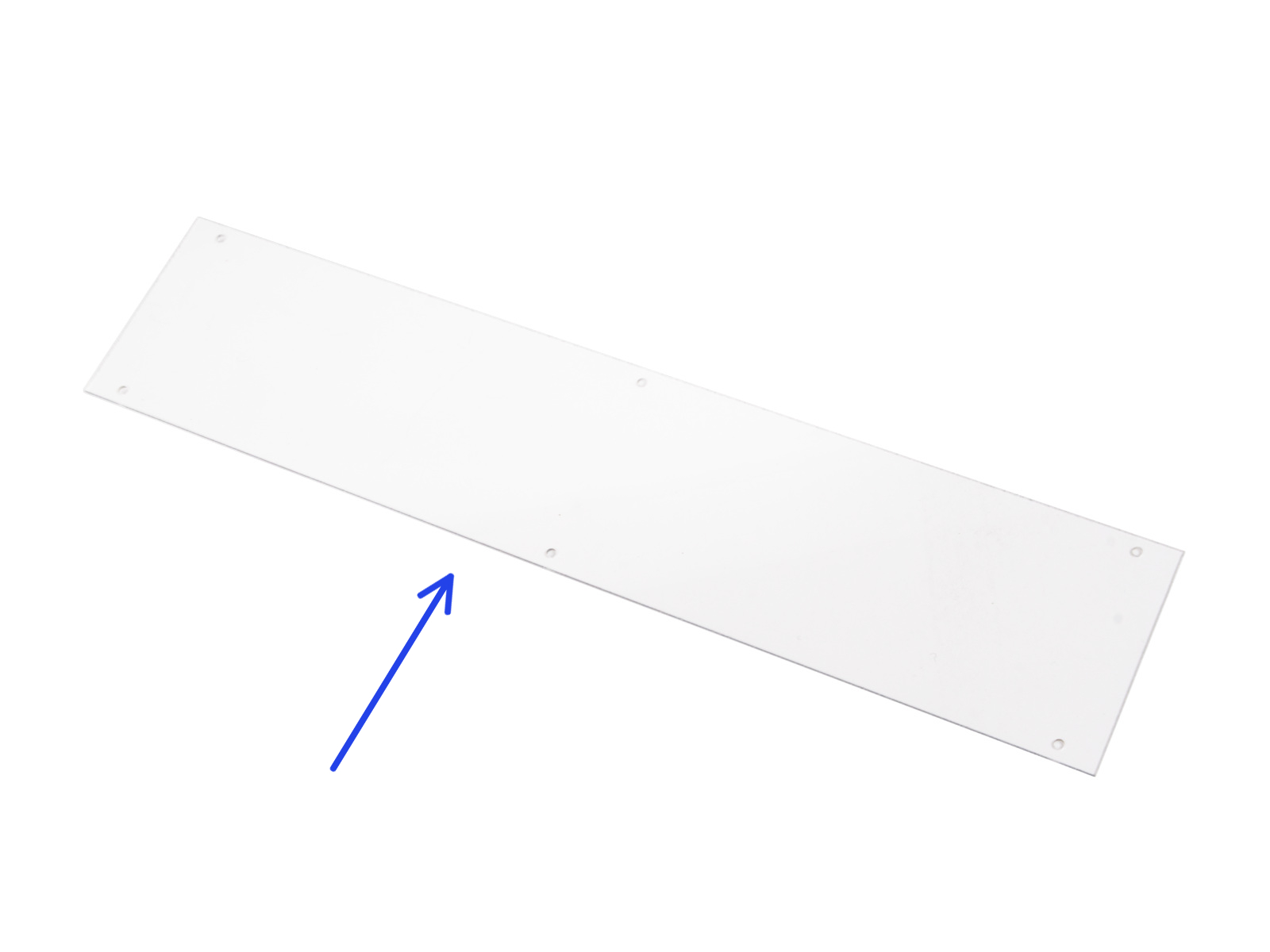
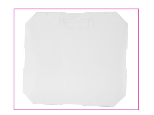
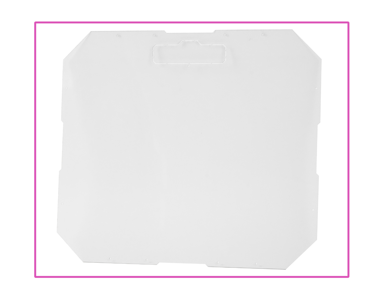
⬢From the inside, carefully place the MINI Top window panel over the rectangular opening in the MINI Top panel.
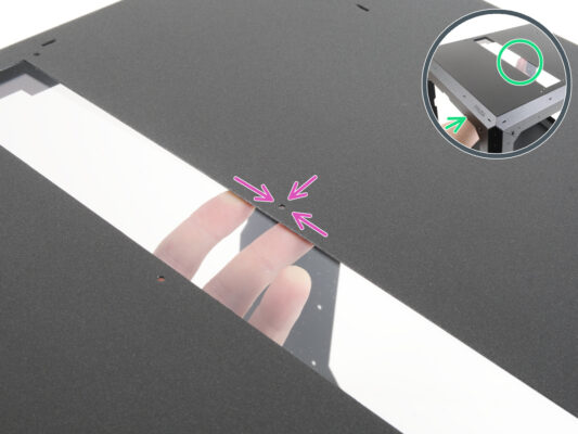
⬢Align the holes of both parts.
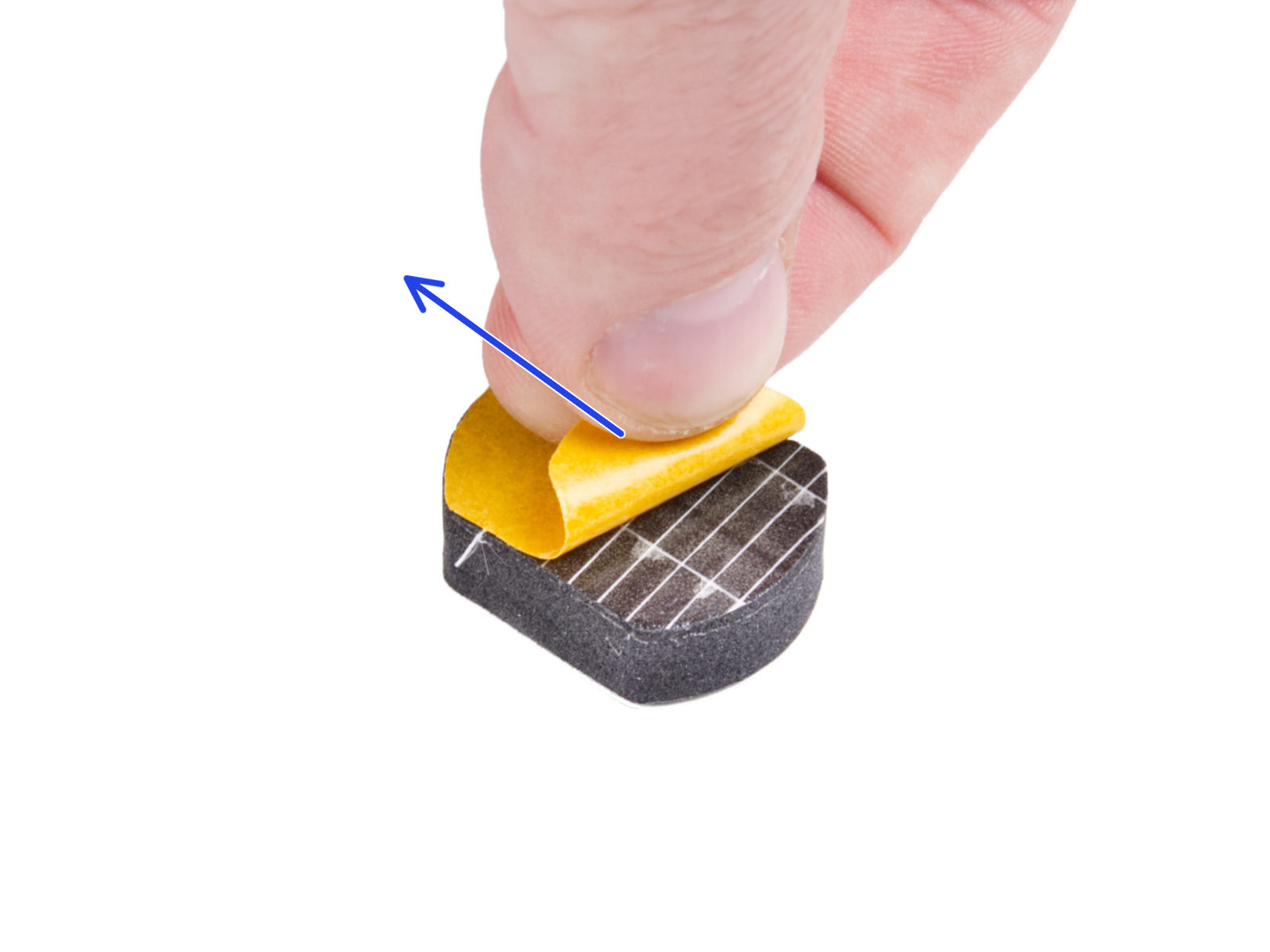
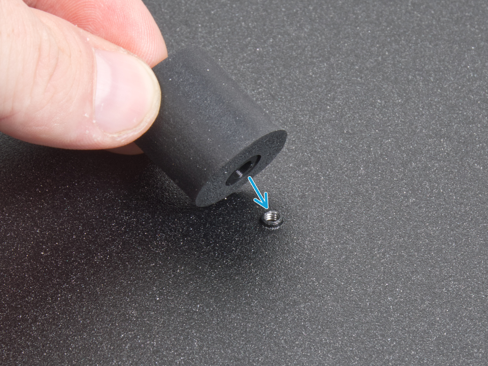
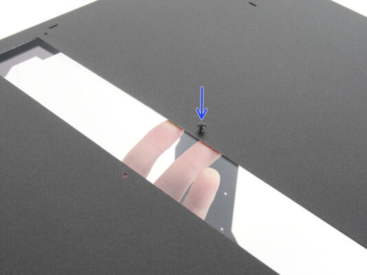
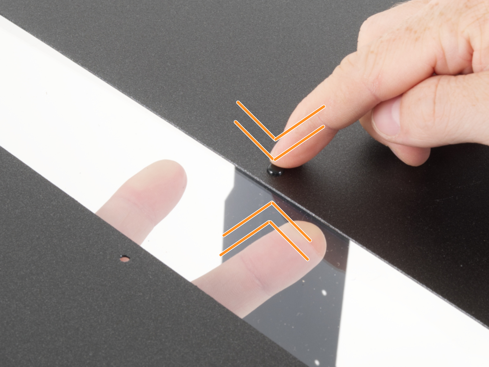
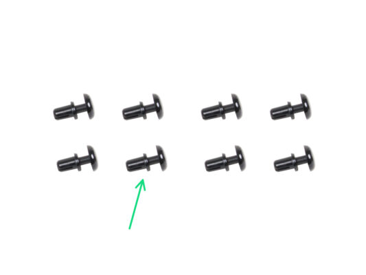
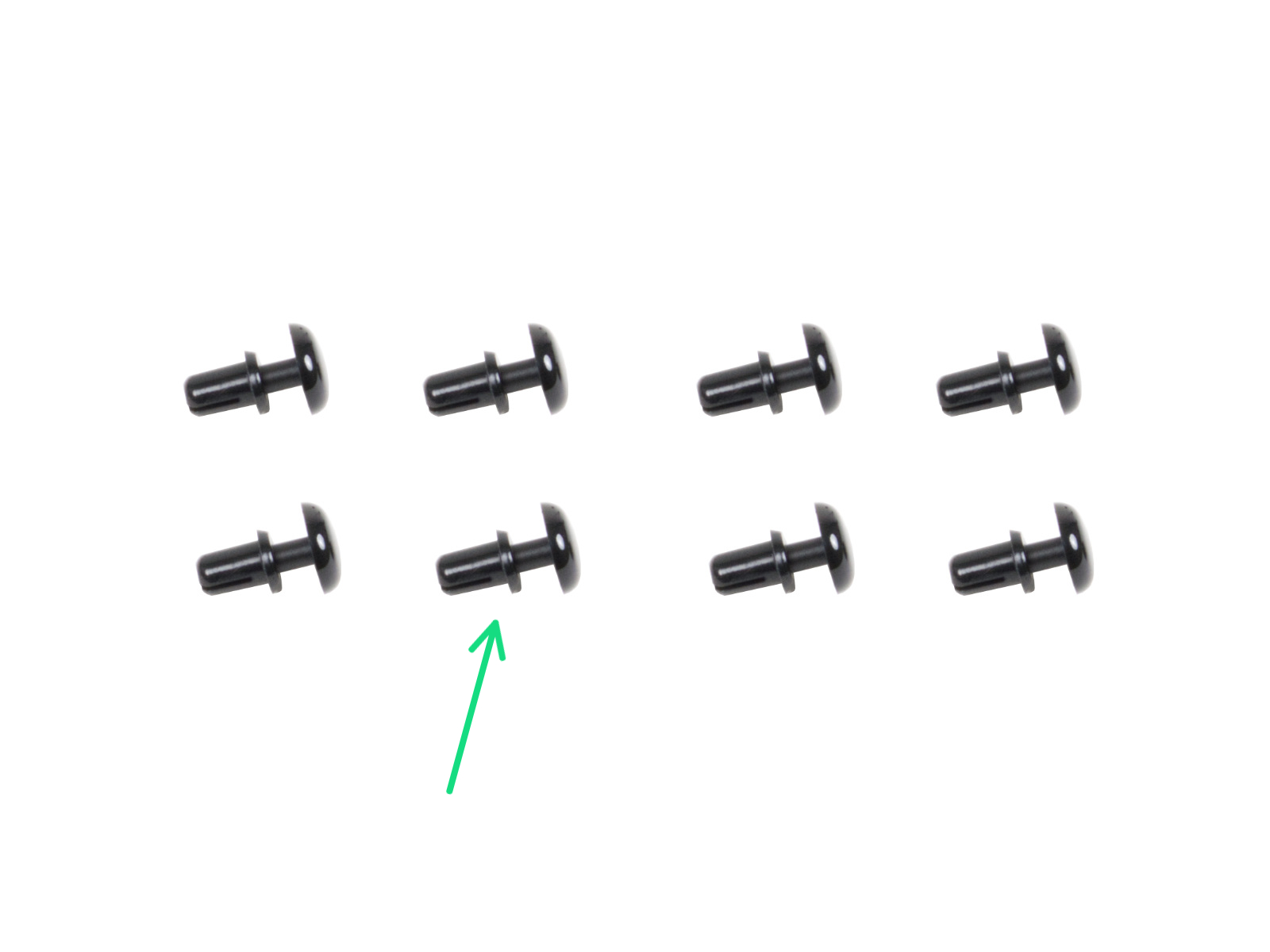
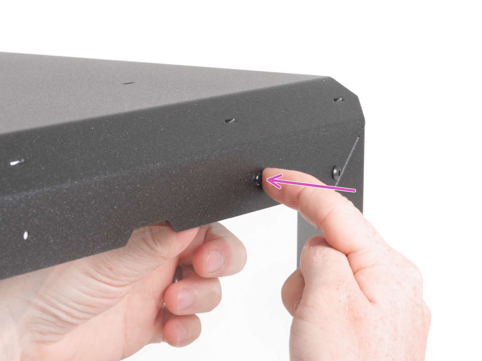
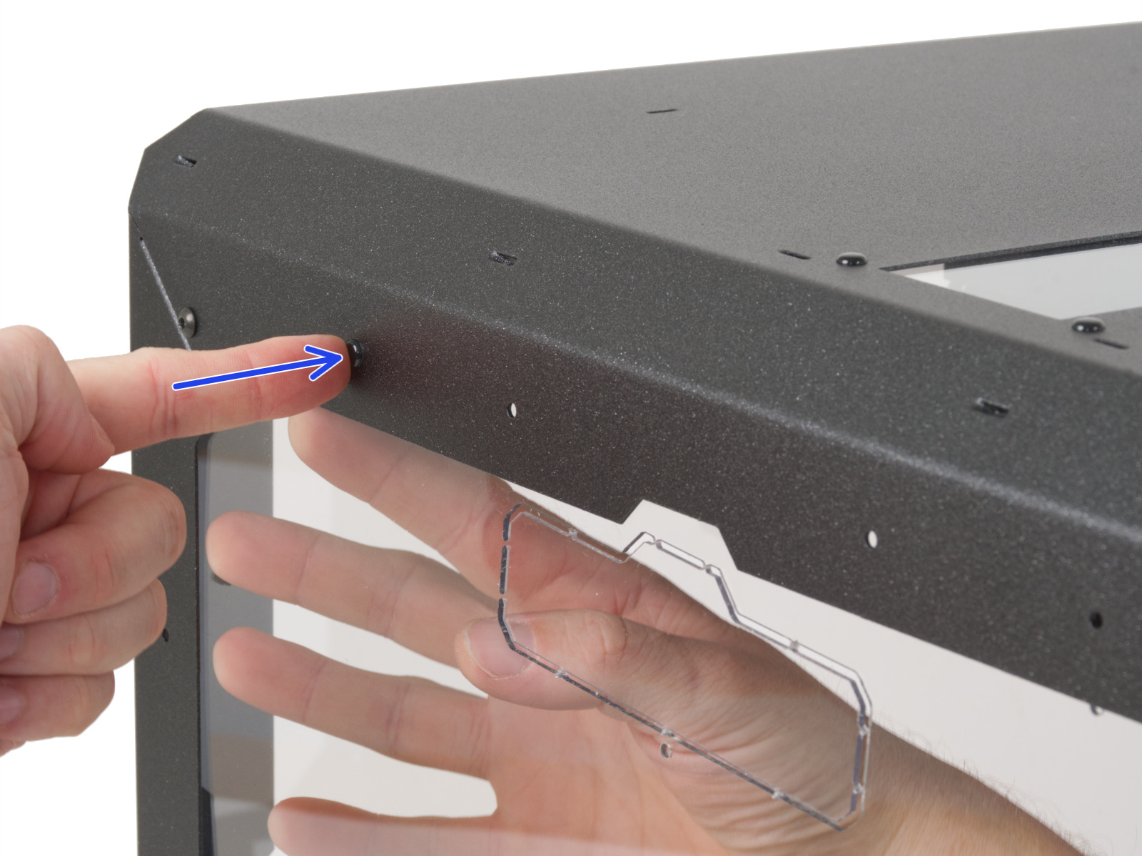
⬢Insert the nylon rivet through the holes of both parts.
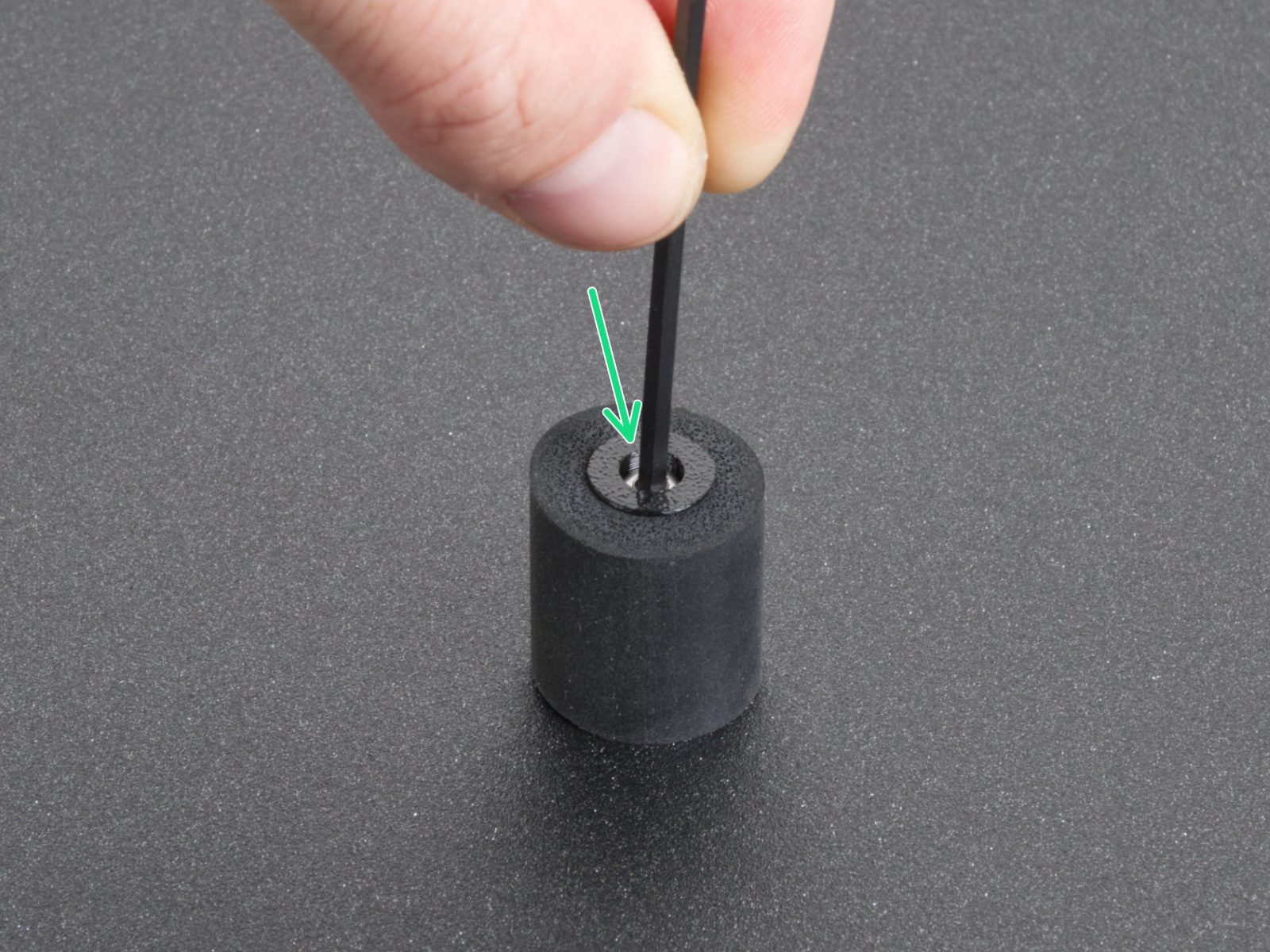
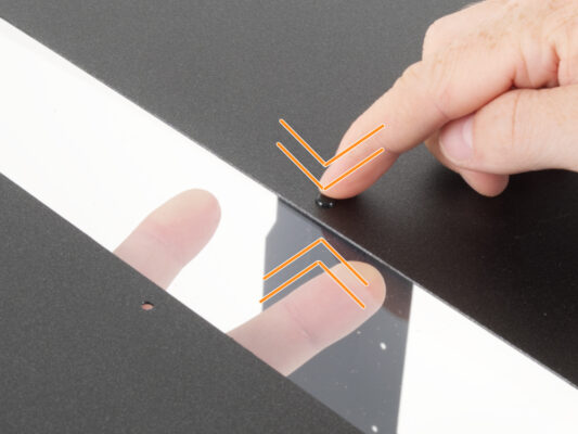
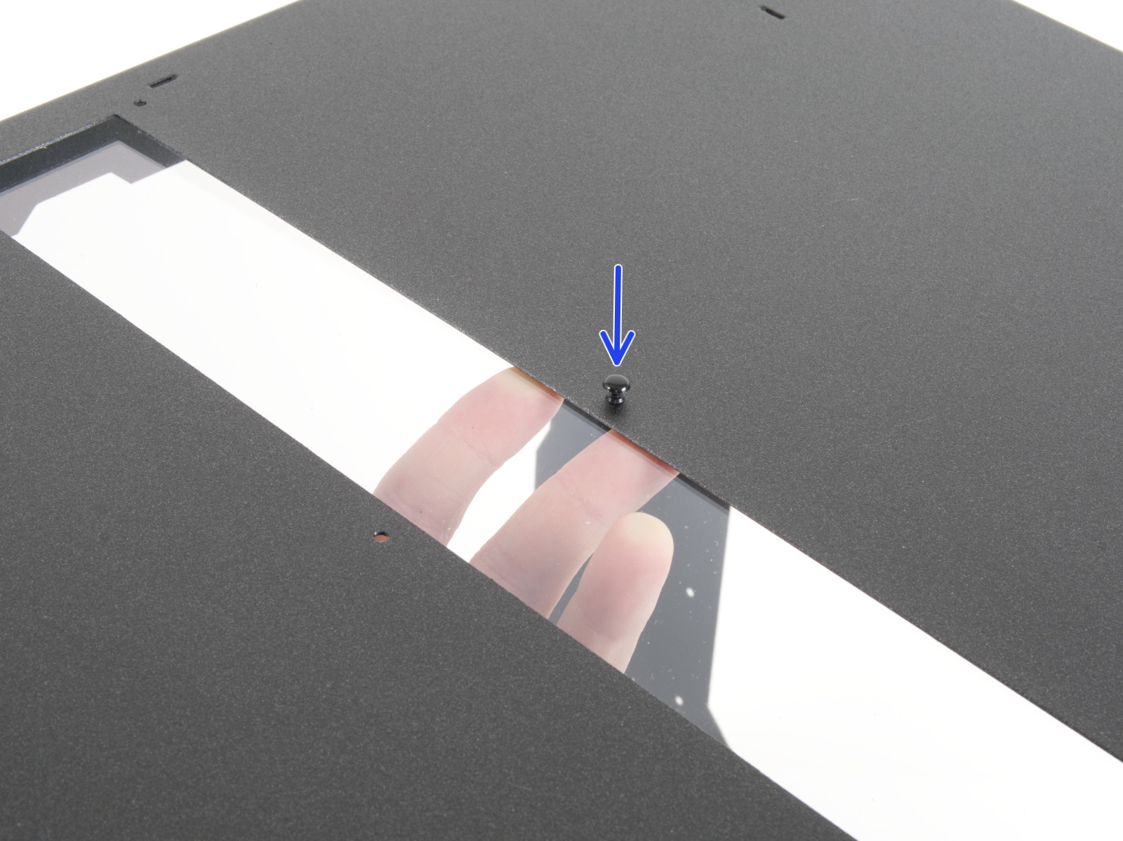
⬢Push on the nylon rivet to secure the window panel in the frame. When pressing on the nylon rivet, apply light pressure on the opposite side, specifically on the MINI Top window panel around the rivet.
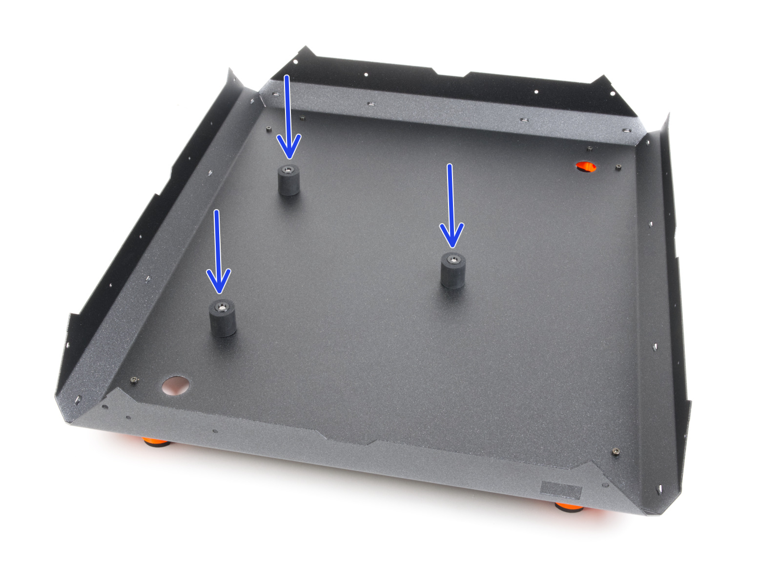
⬢Repeat this procedure for the remaining holes in the opening.
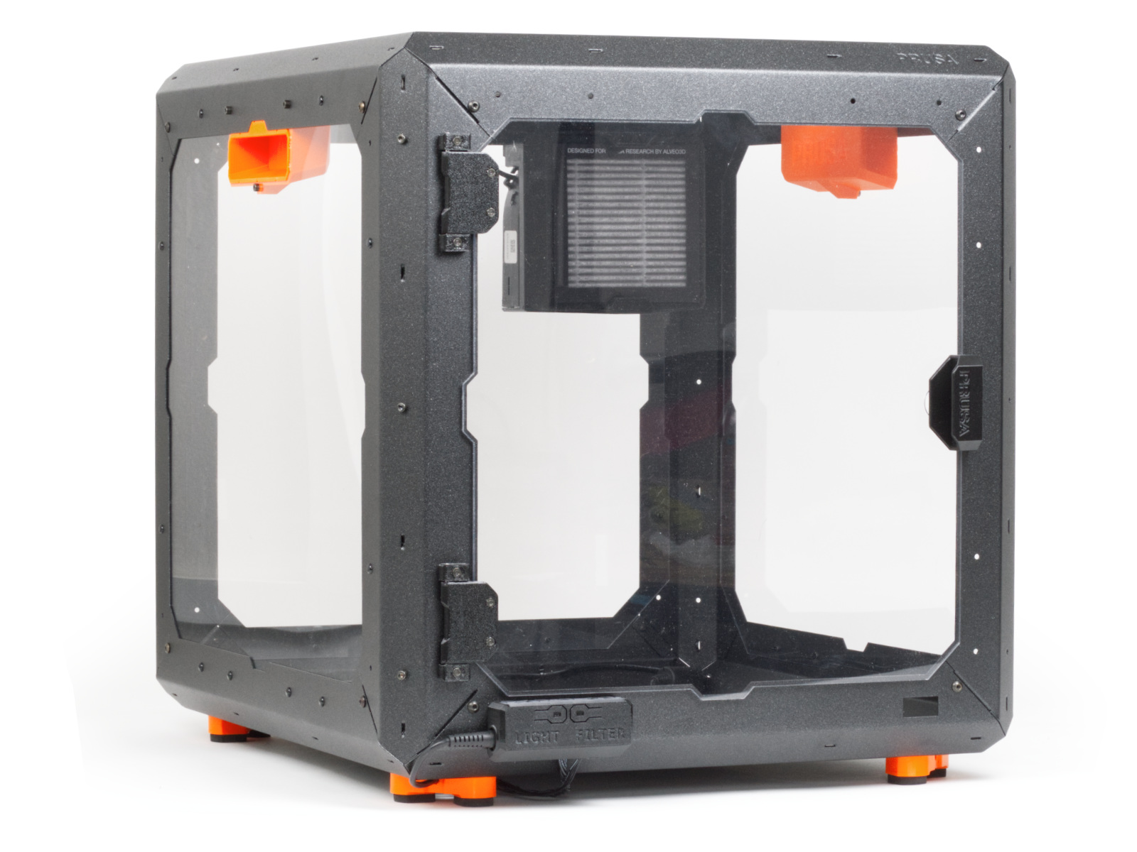
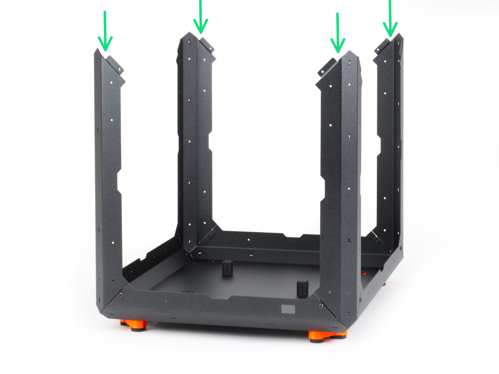
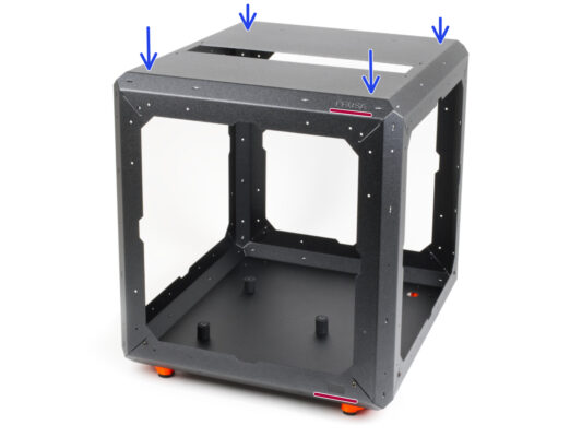
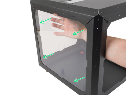
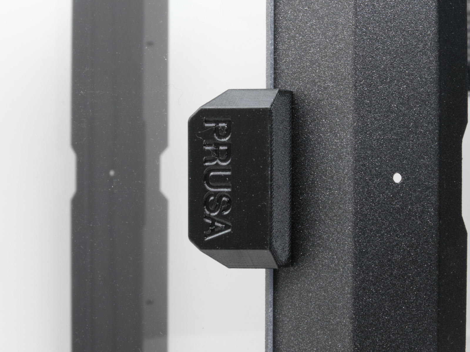
⬢Turn the Enclosure sideways so that the rear side (without the PRUSA logo) is facing you.
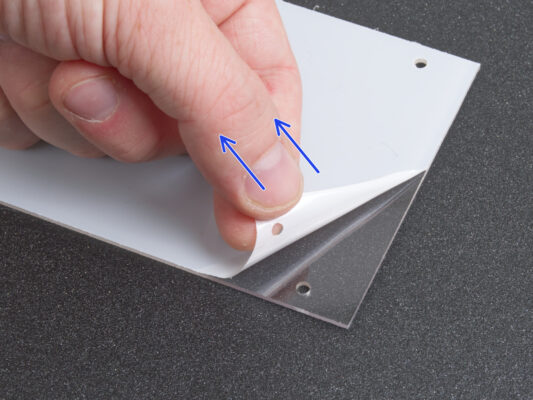
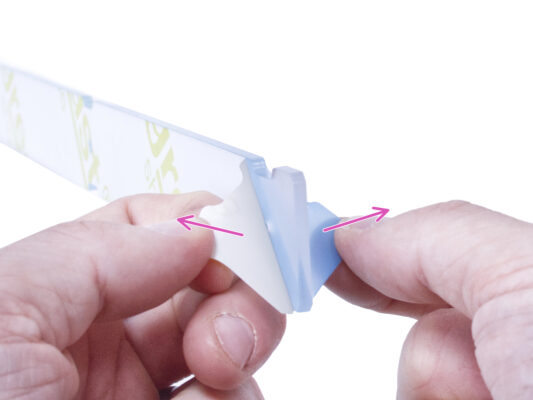
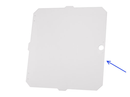
⬢Peel off the protective layers from both sides of the MINI Back panel.
Be careful; the panel is very susceptible to scratches.
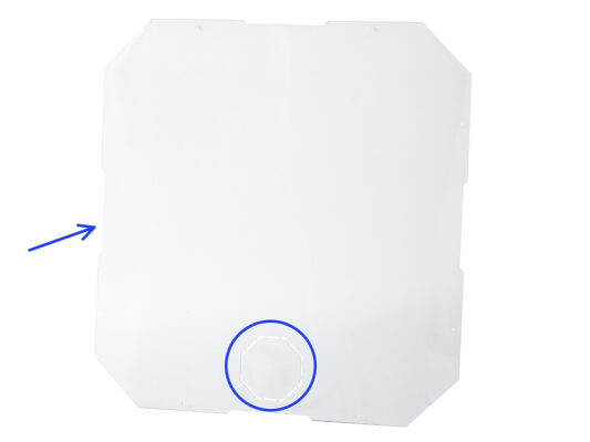
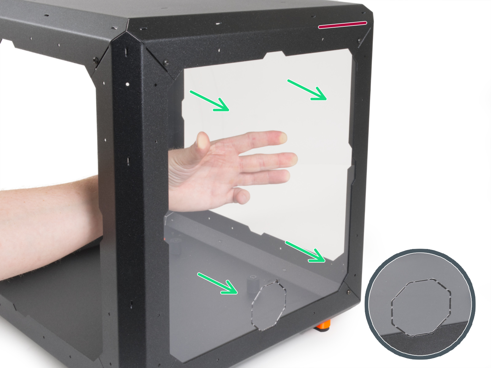
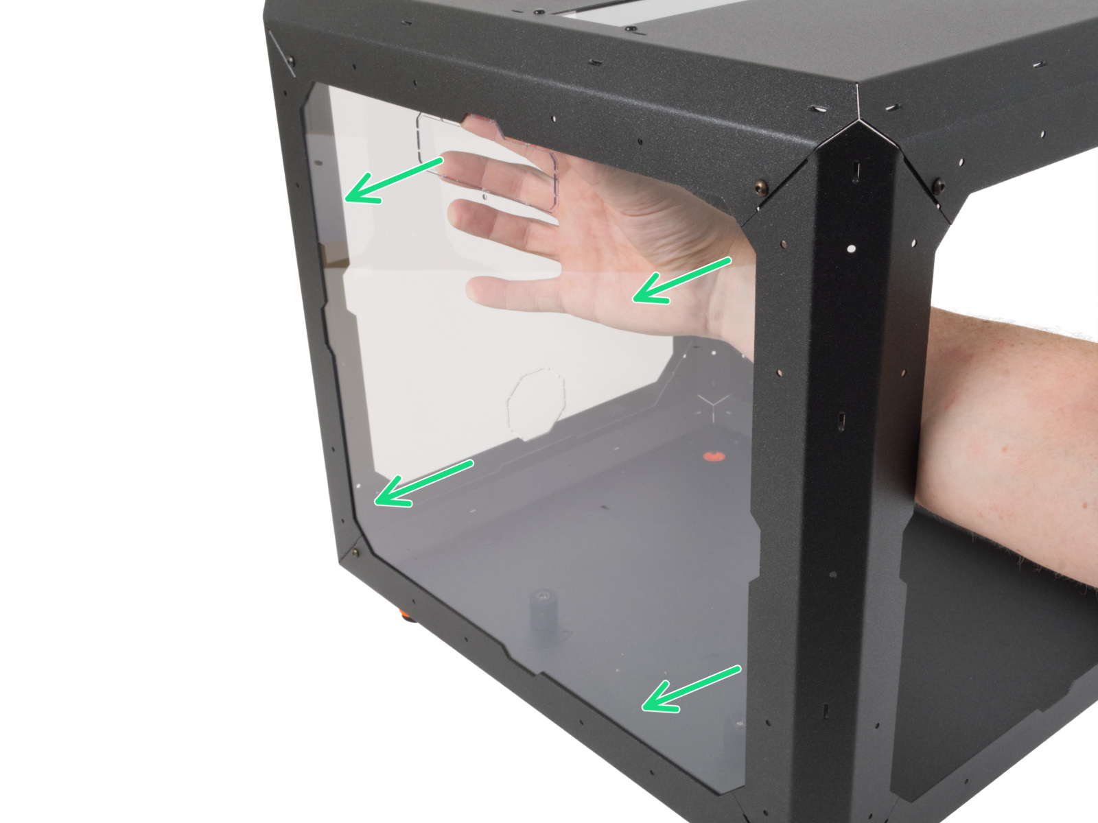
⬢From the inside, carefully place the MINI Back panel to the rear Enclosure "frame".
Mind the correct orientation of the panel. The octagonal cutout must be at the bottom.
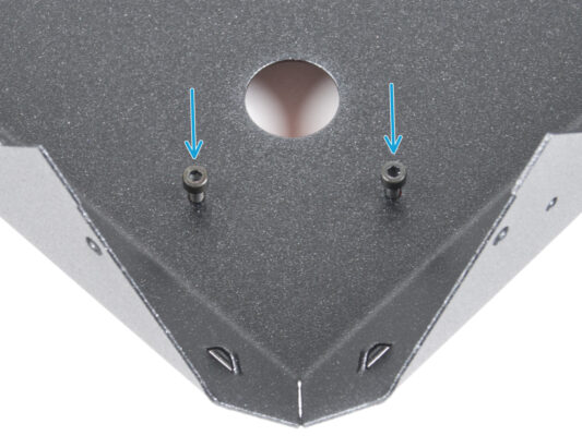
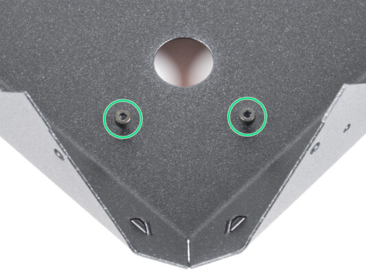
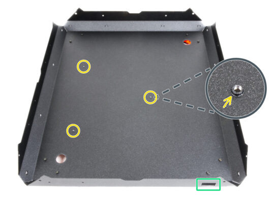
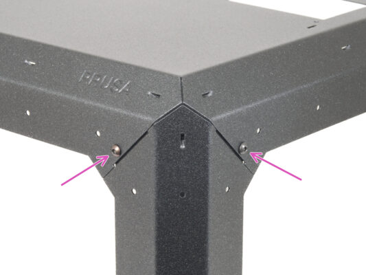
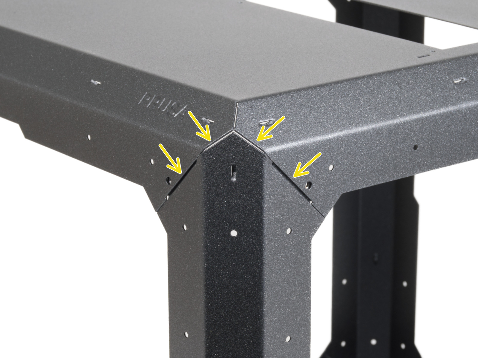
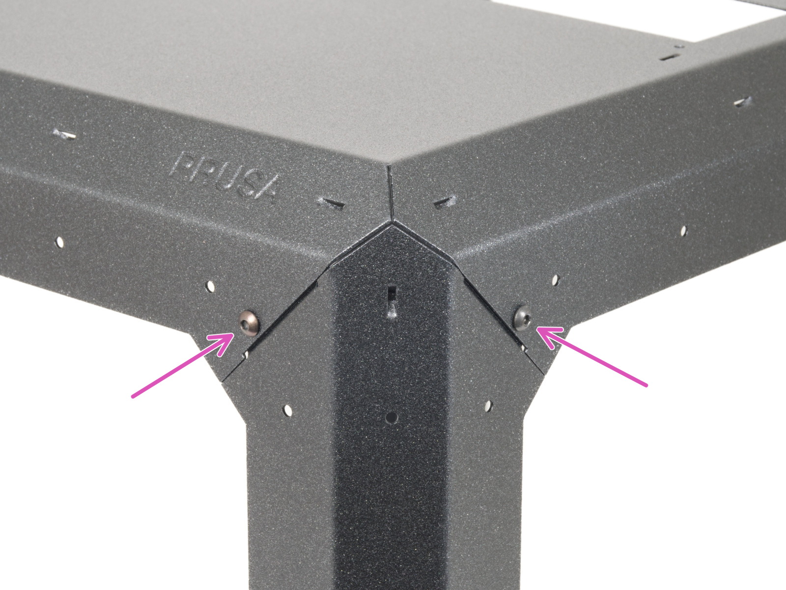
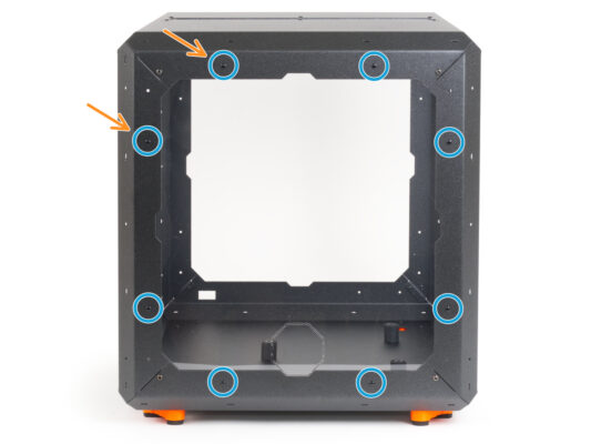
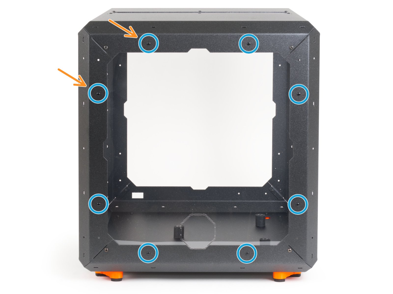
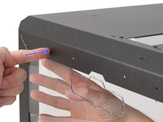
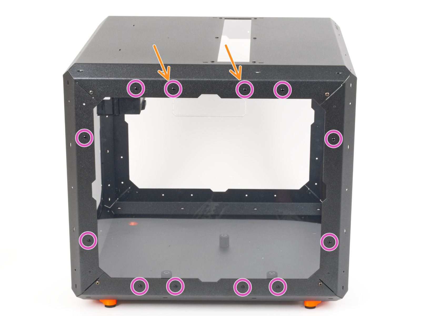
⬢Align the holes of the panel and the Enclosure "frame" and secure it with one nylon rivet near the top right corner. When pressing on the nylon rivet, apply light pressure on the opposite side, specifically on the MINI Back panel around the rivet.
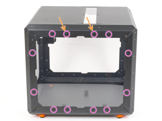
⬢In this way, secure the panel around the entire perimeter.
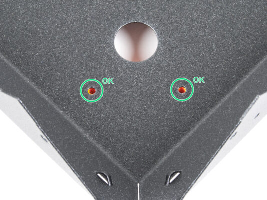
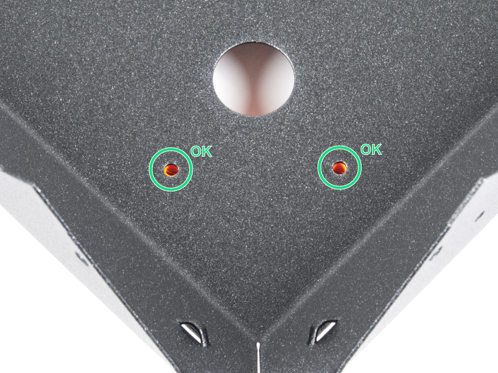
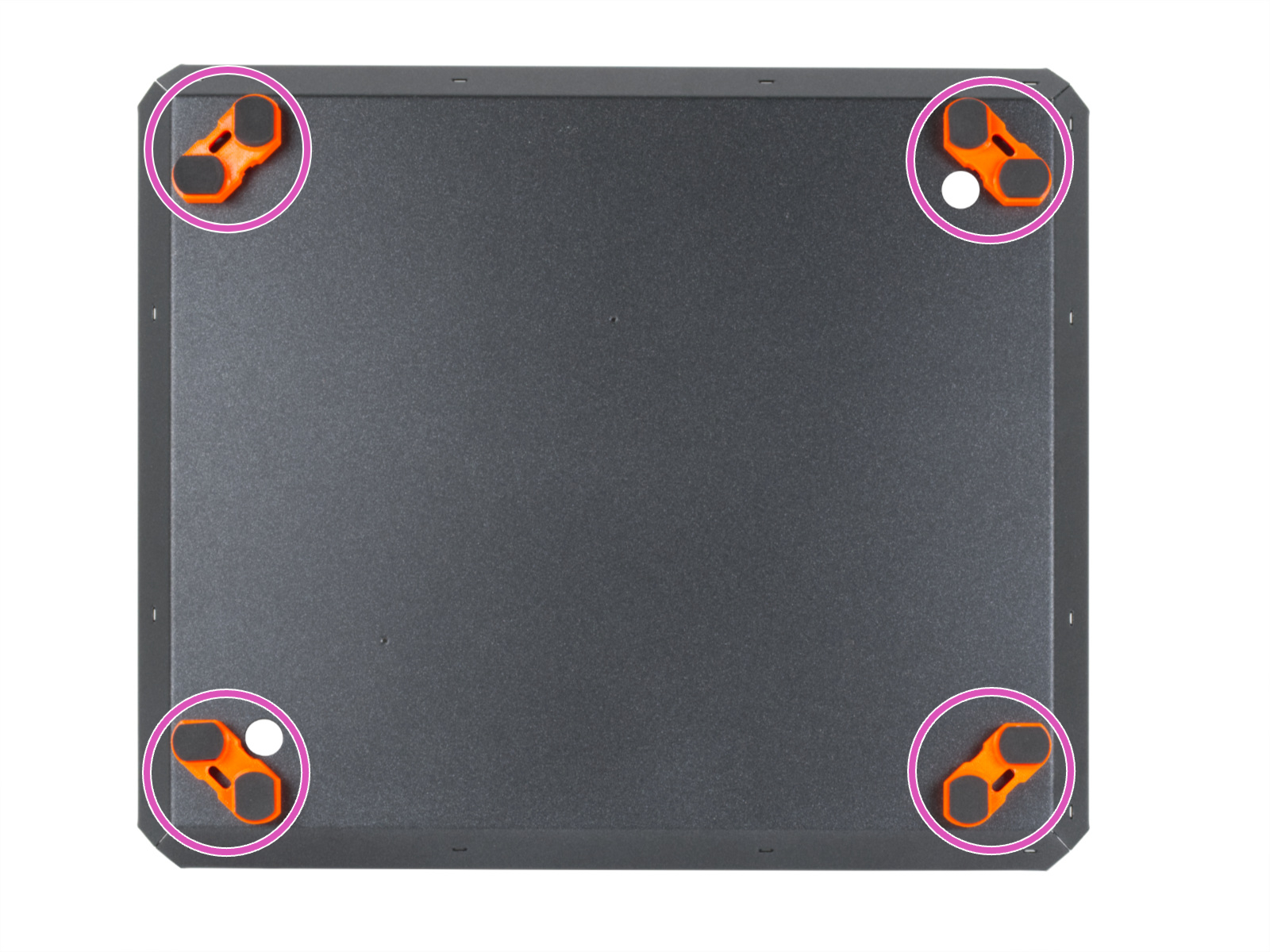
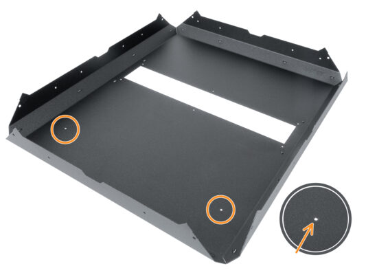
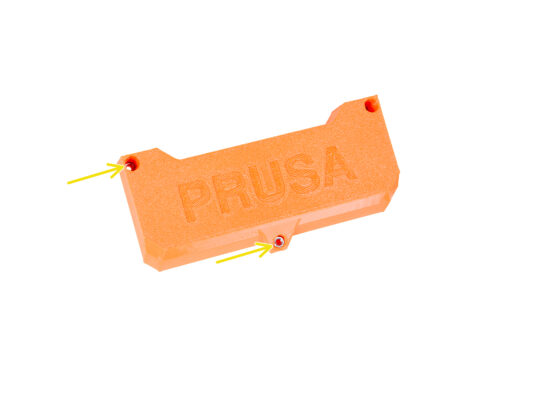
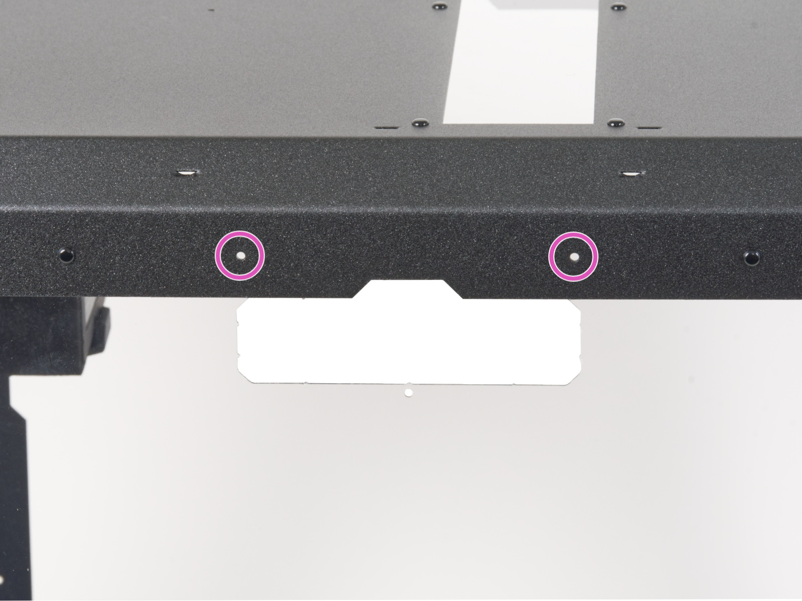
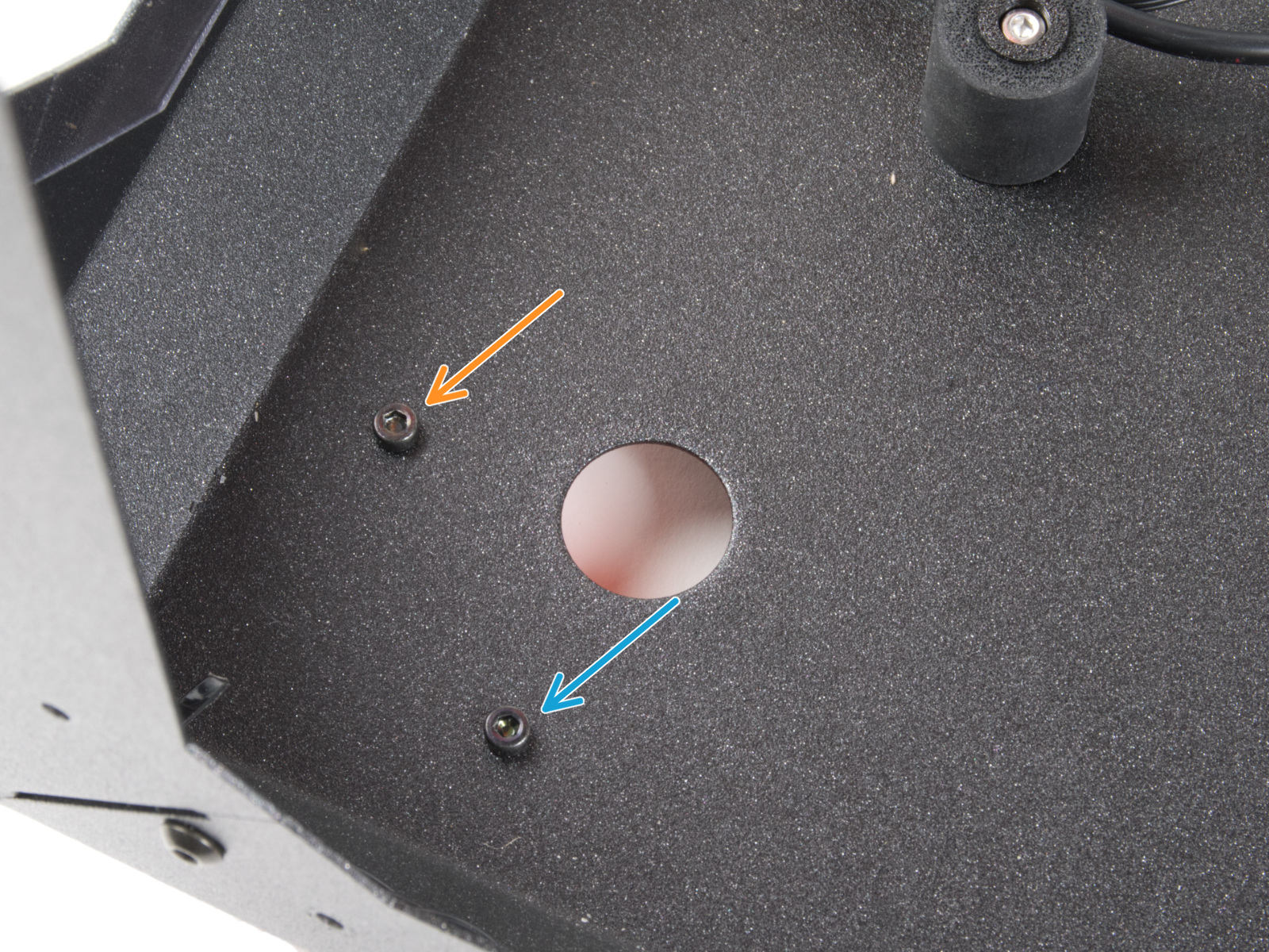
⬢If you are going to install the Advanced filtration system optional add-on, leave the marked holes empty.
NOTE: The following instructions are only for those who have purchased this optional add-on with the MINI Enclosure. If you have not purchased this add-on, please proceed to step Side panels: parts preparation
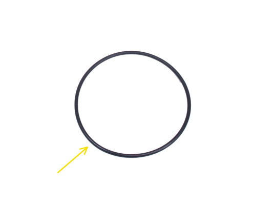
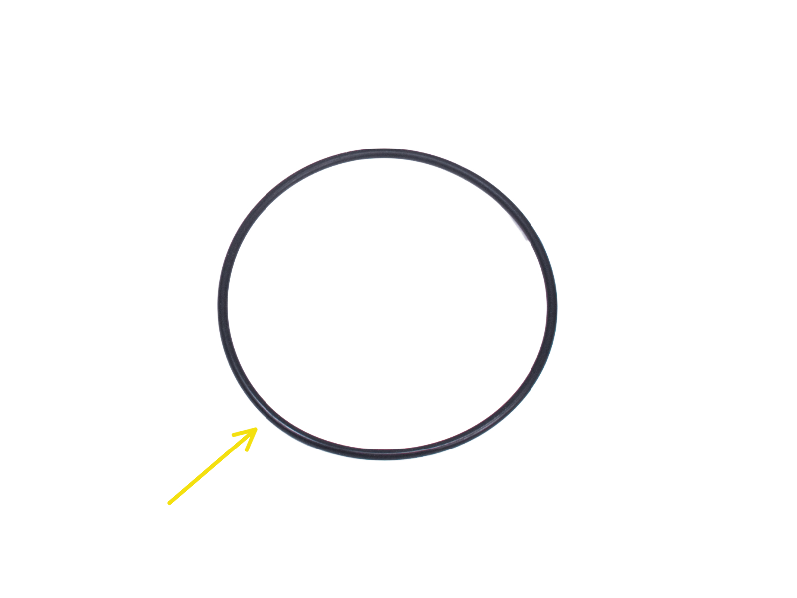
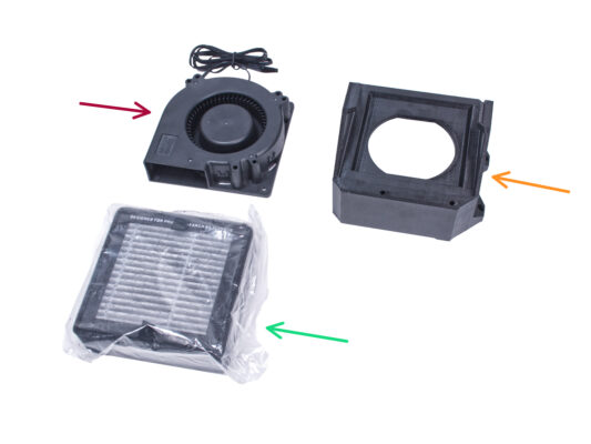
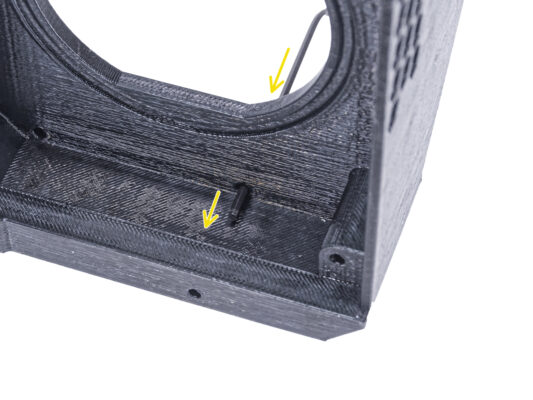
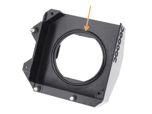
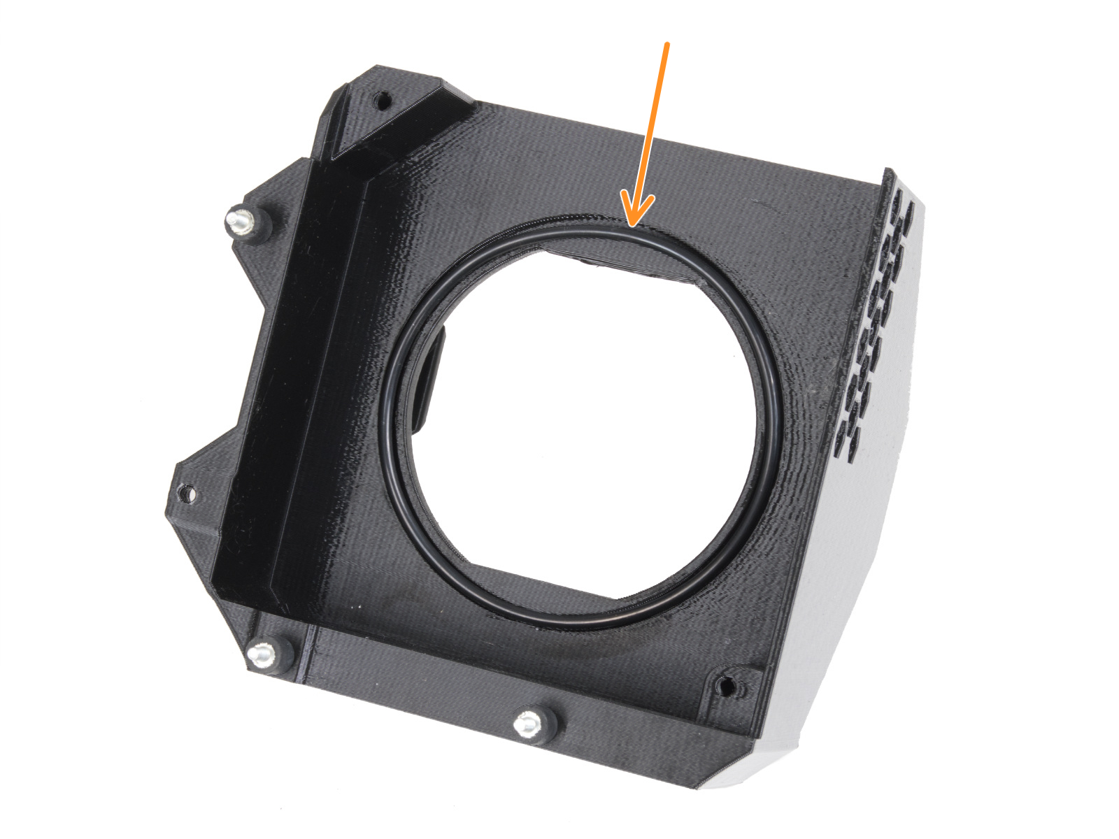
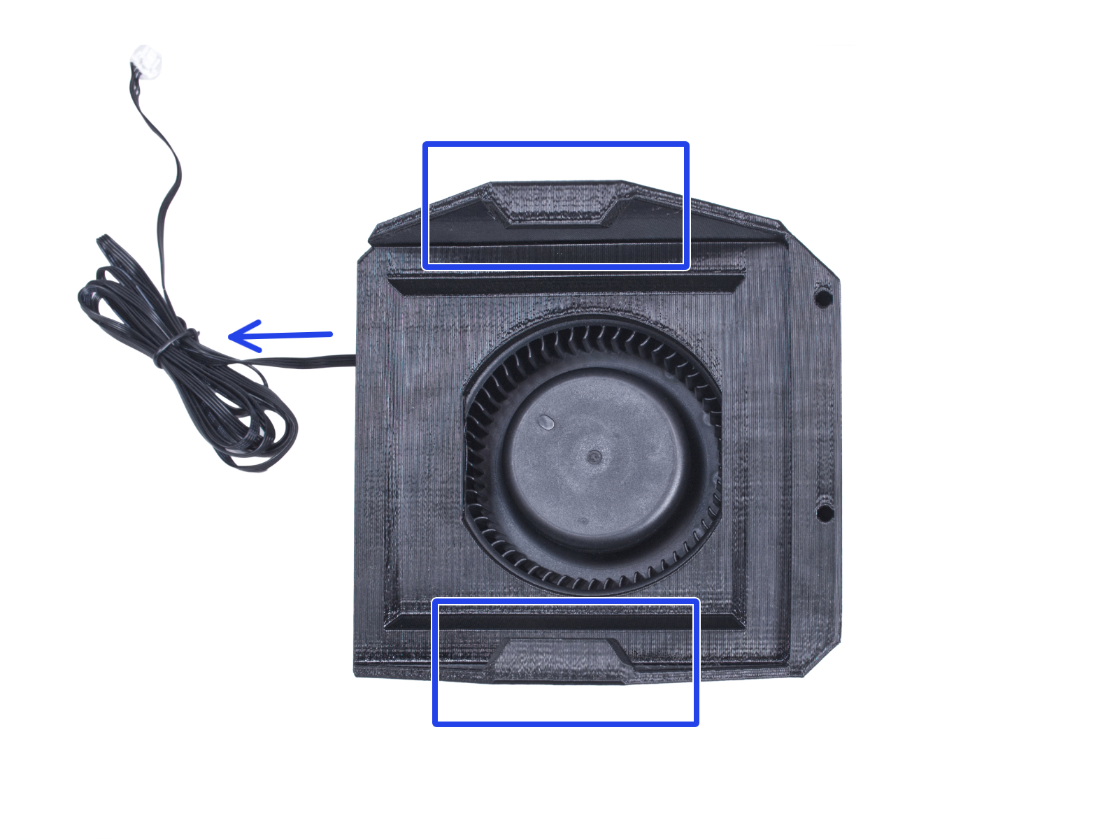
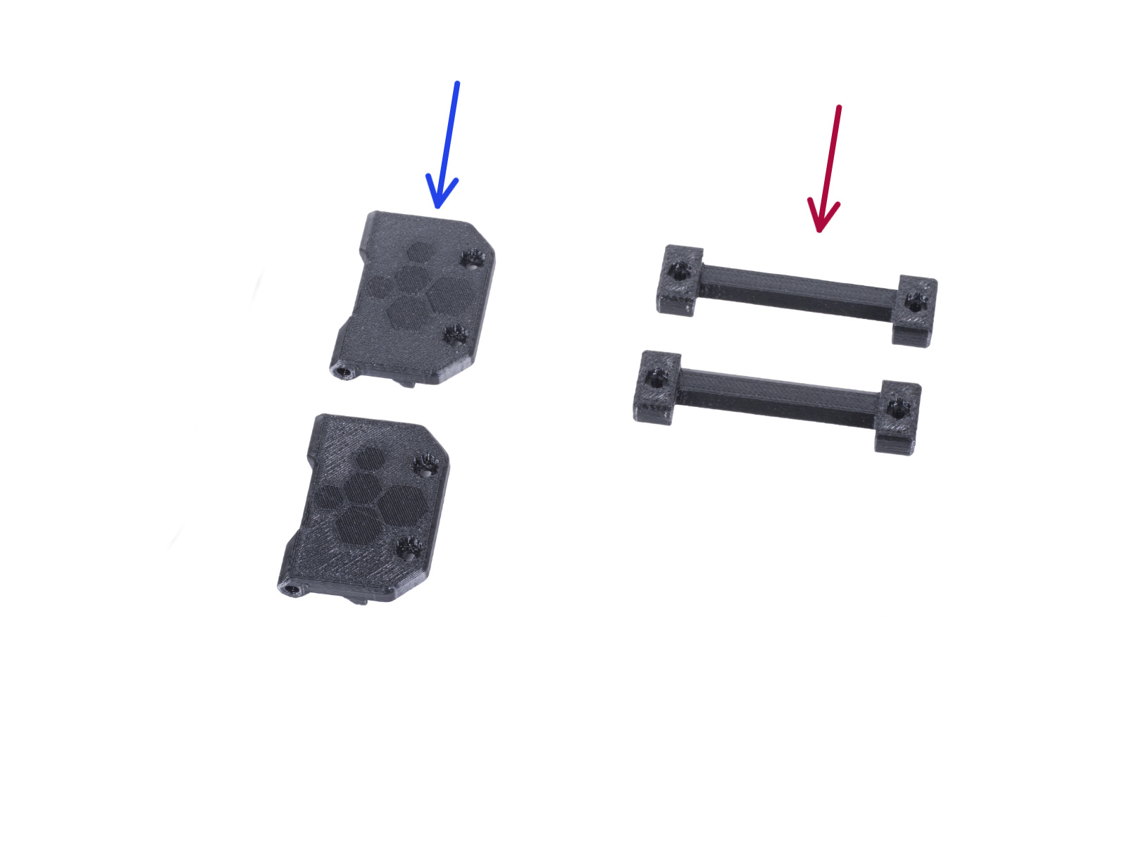
⬢Placez le joint torique du ventilateur radial dans le Filter-Bracket.
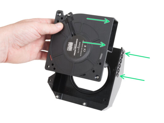
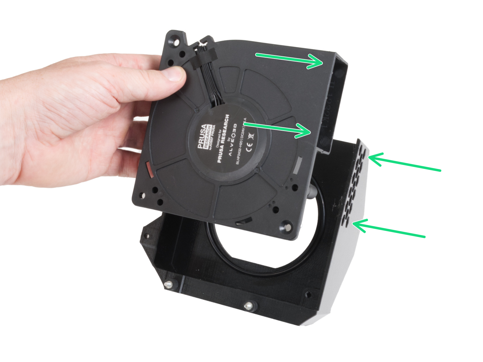
⬢Insérez le ventilateur radial haute pression dans le Filter-Bracket de sorte que la sortie du ventilateur soit face aux trous hexagonaux de la pièce imprimée.
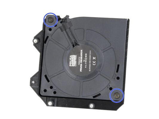
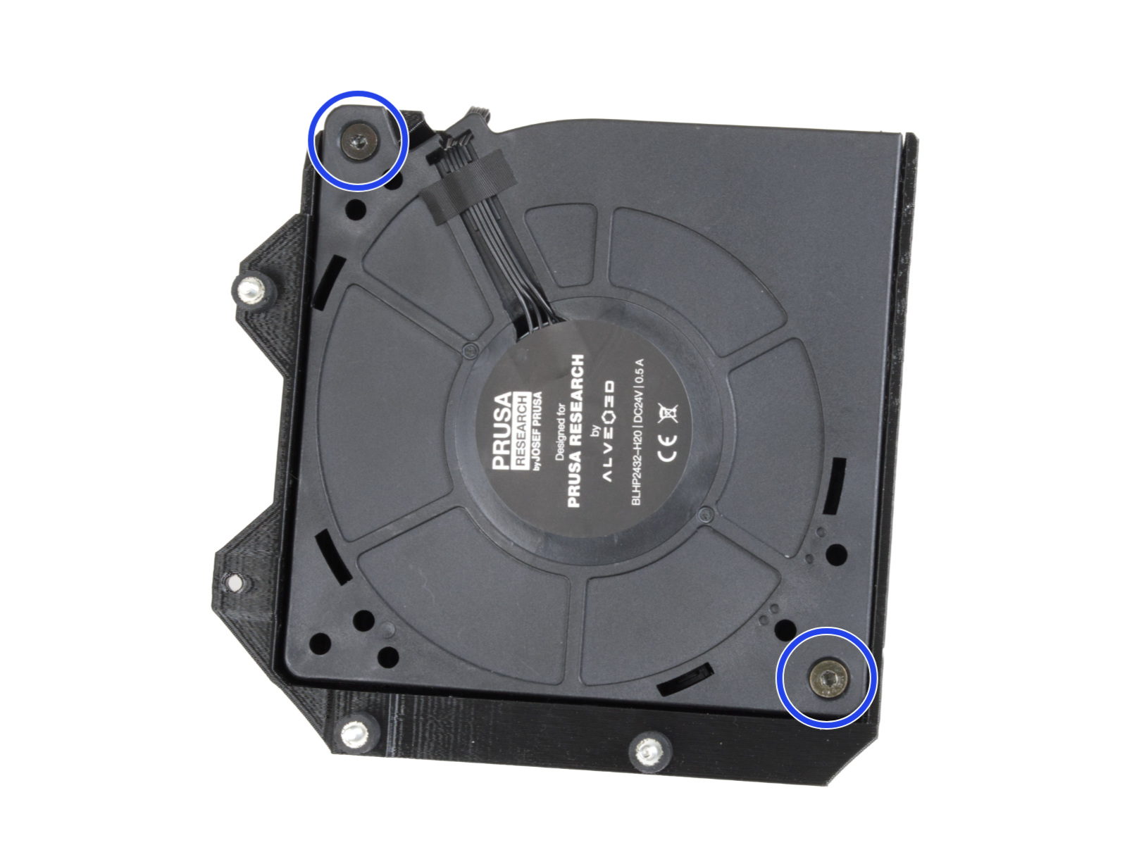
⬢Assemblez les deux pièces avec deux vis à tête fraisée M4x16b.
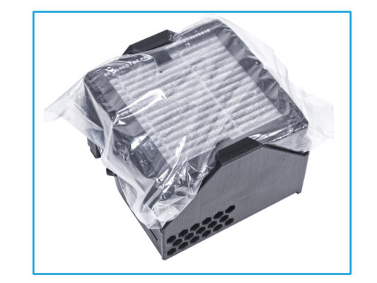
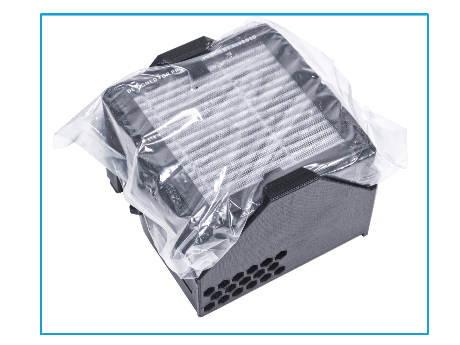
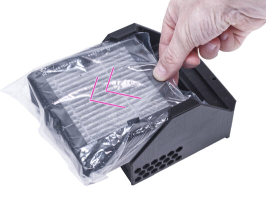
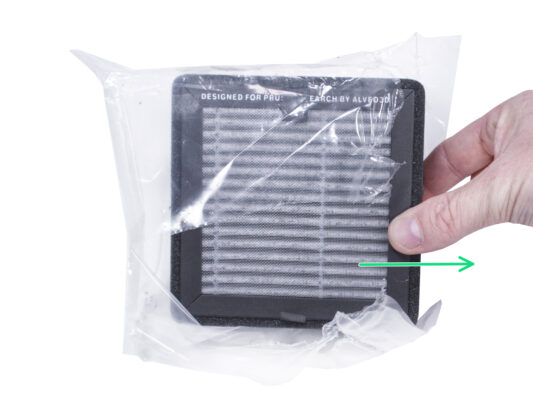
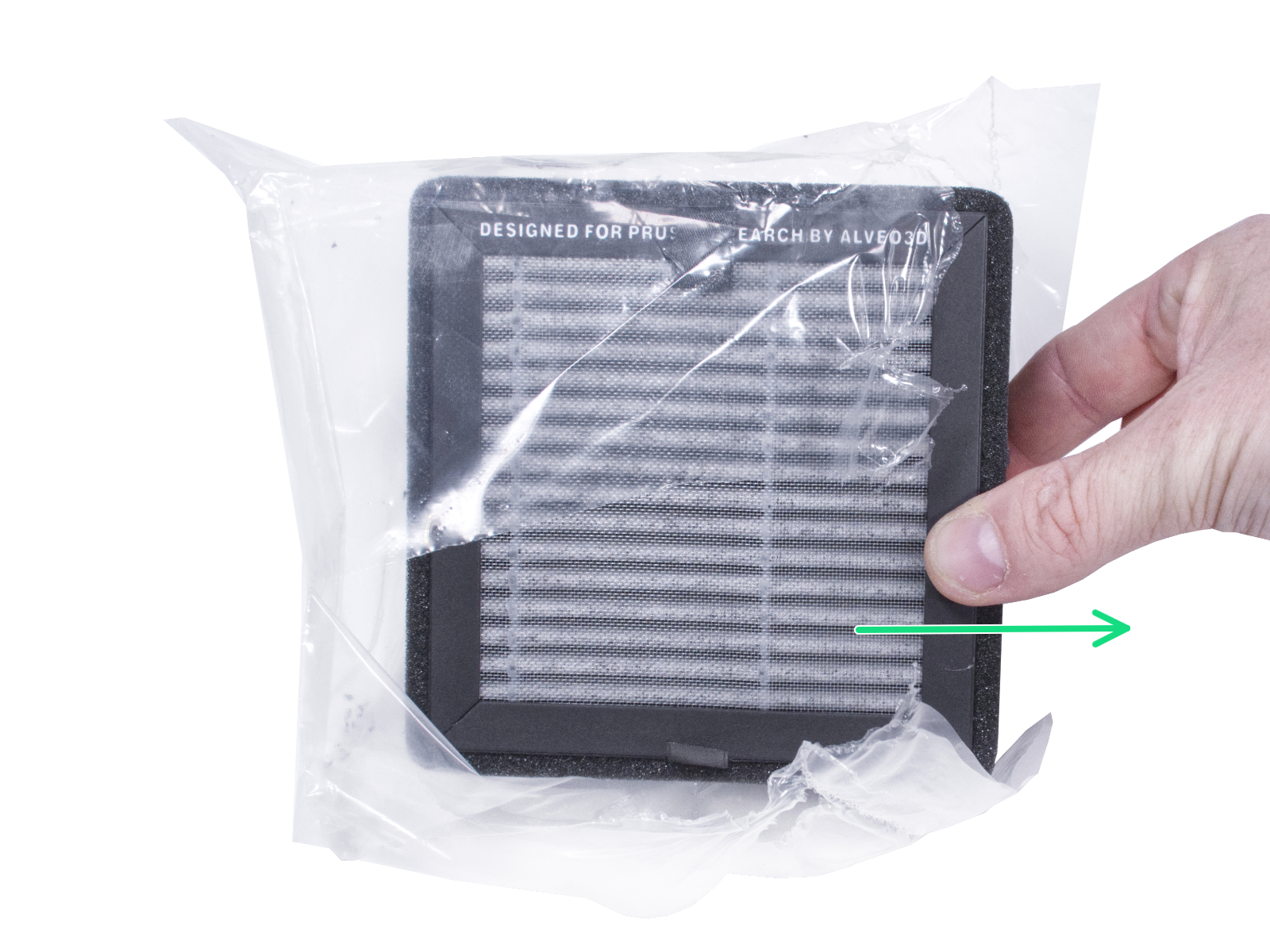
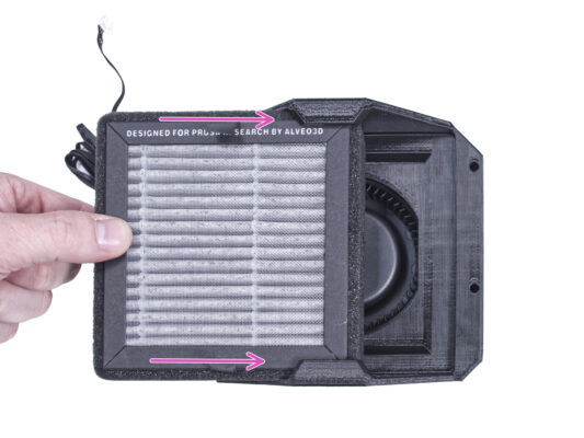
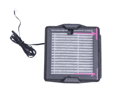
⬢Déchirez le sac du filtre et sortez le filtre HEPA.
Manipulez le filtre avec précaution. Si la surface HEPA (la surface plissée blanche) est endommagée, le filtre perdra son efficacité. Protégez vos mains lorsque vous retirez le filtre usagé et placez-le dans un sac en plastique. Un filtre saturé n'est pas recyclable.
NOTE: The following instructions are only for those who have purchased this optional add-on with the MINI Enclosure. If you have not purchased this add-on, please proceed to step Door hinges: parts preparation
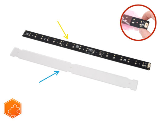
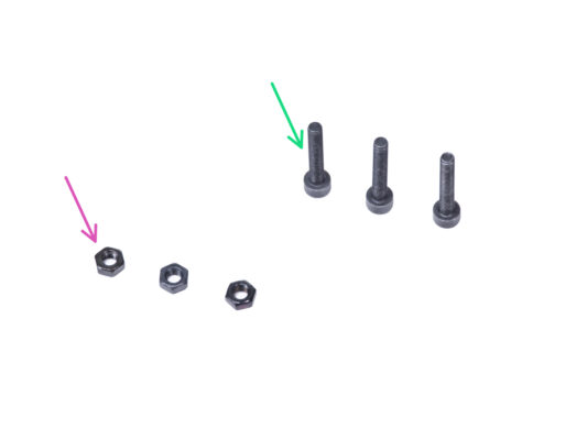
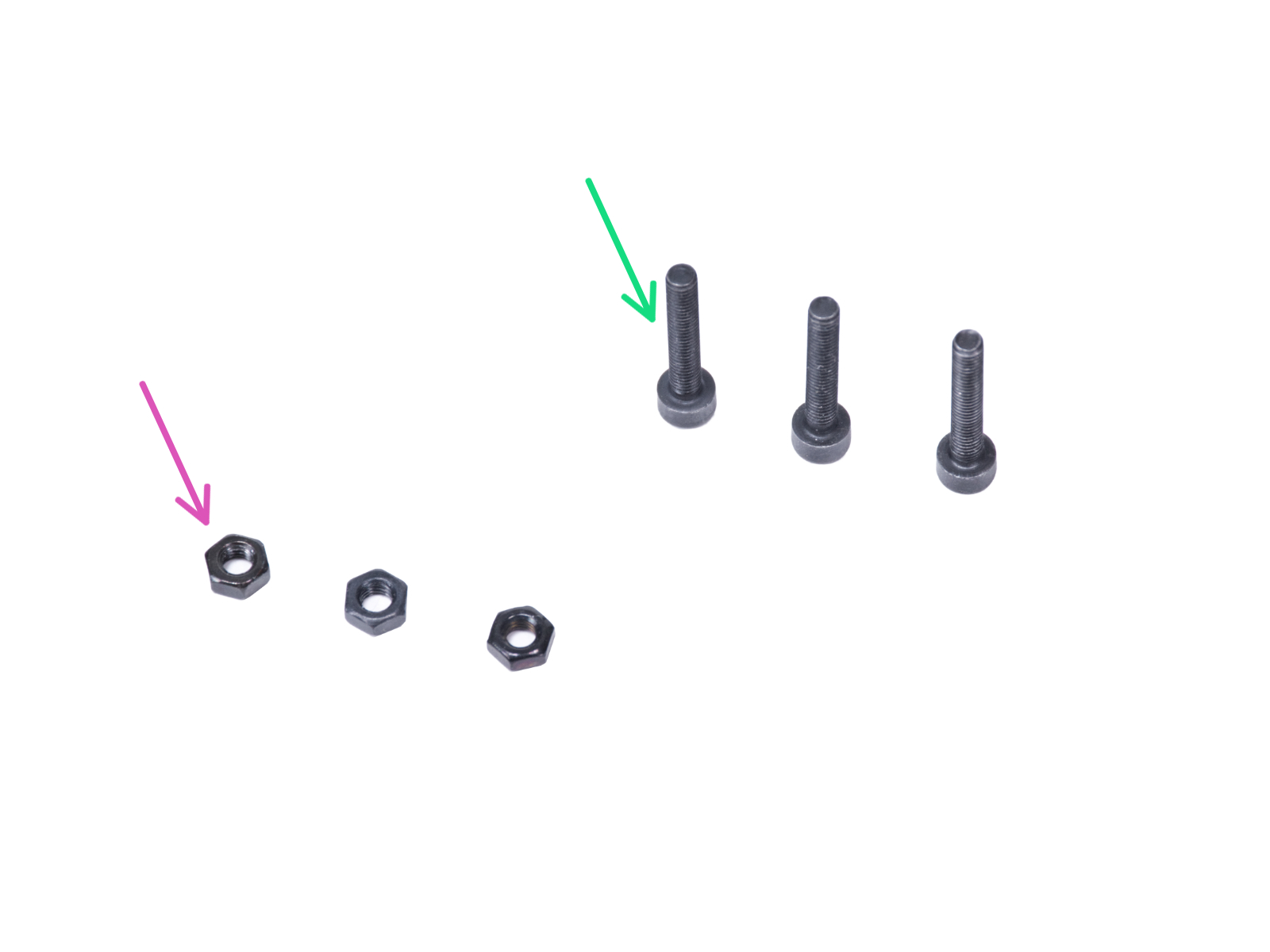
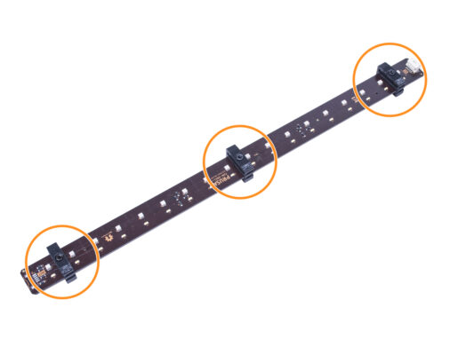
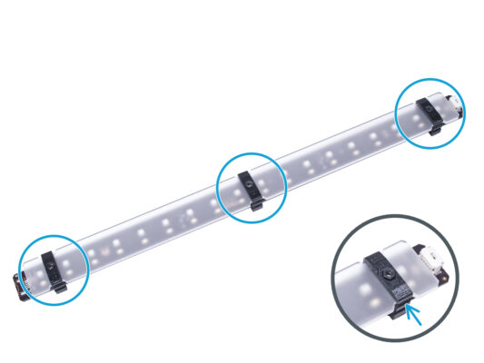
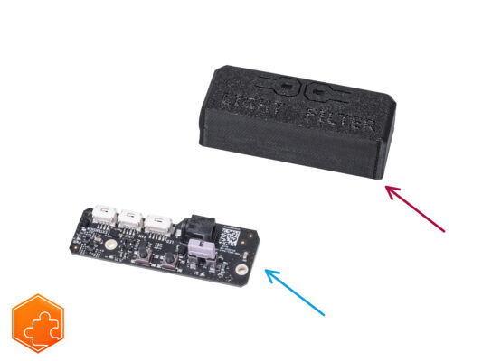
⬢LED Stick Board (1x) WARNING: Make sure to protect the electronics against electrostatic discharge (ESD). Always unpack the electronics right before you need them!
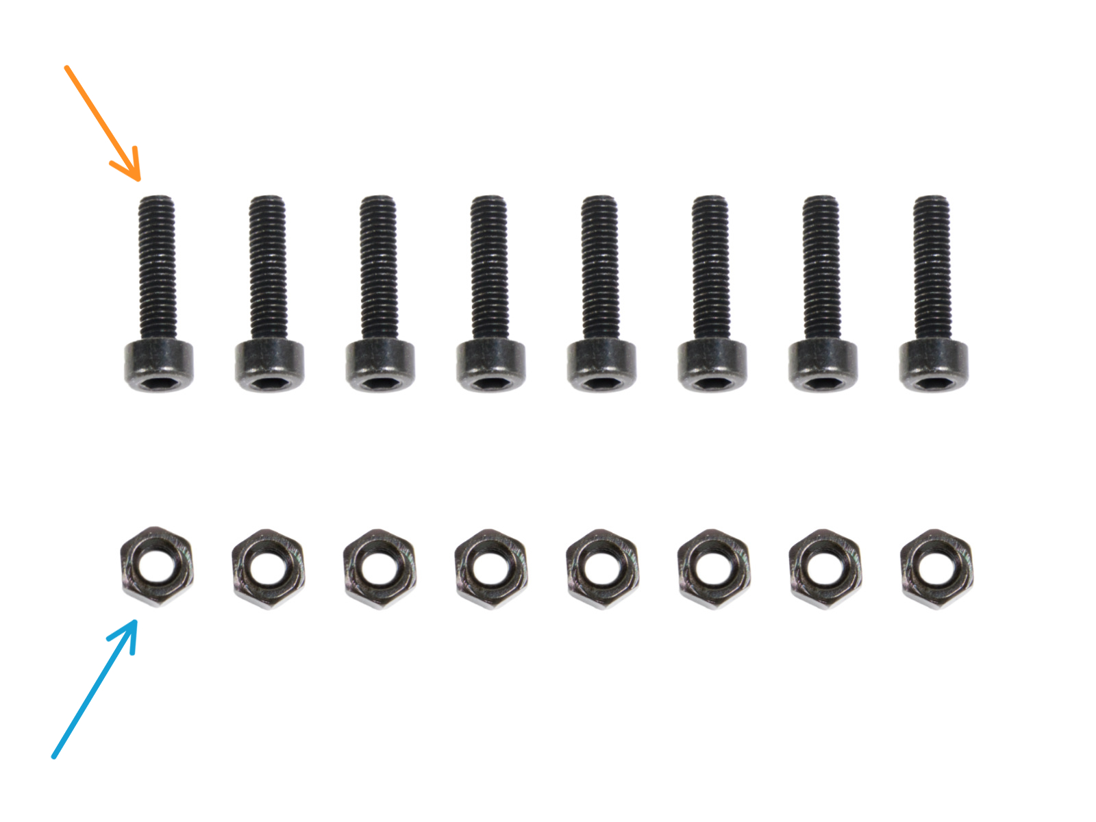
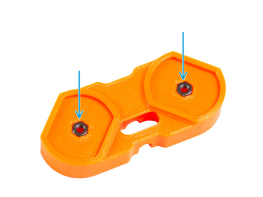
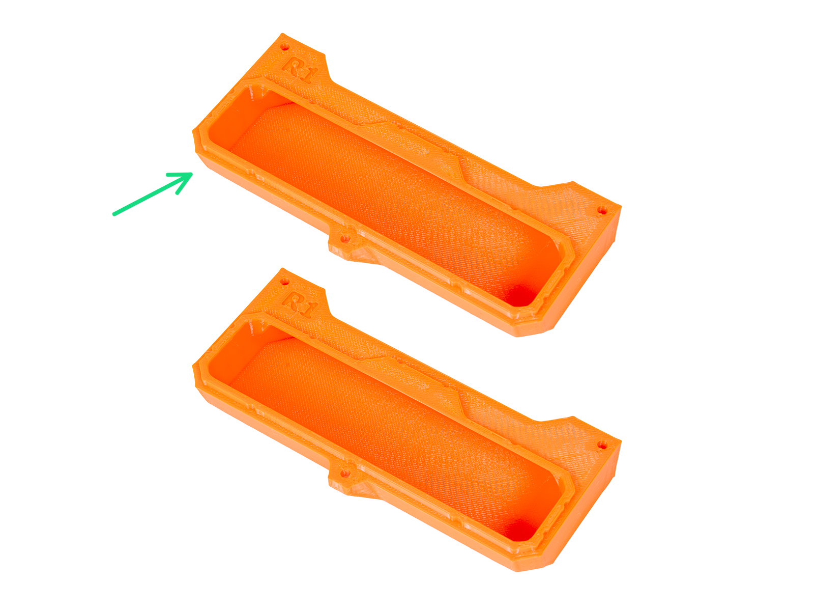
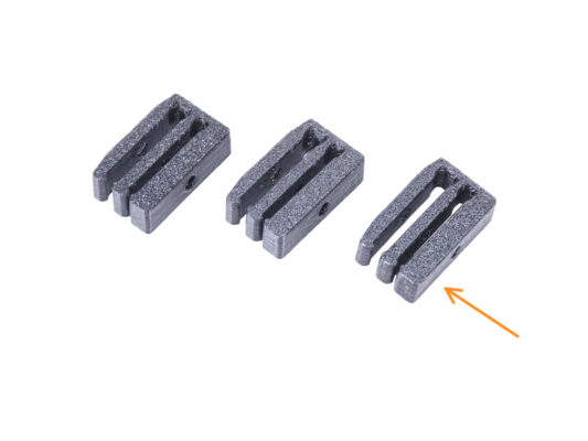
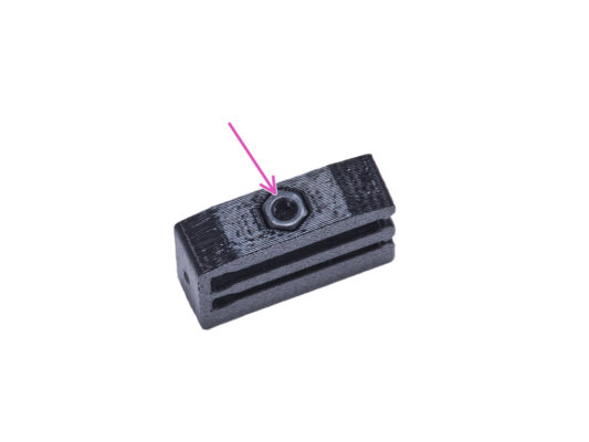
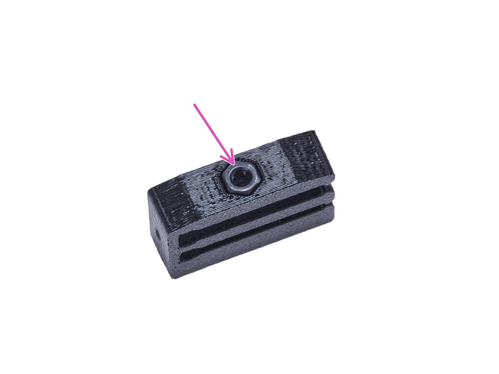
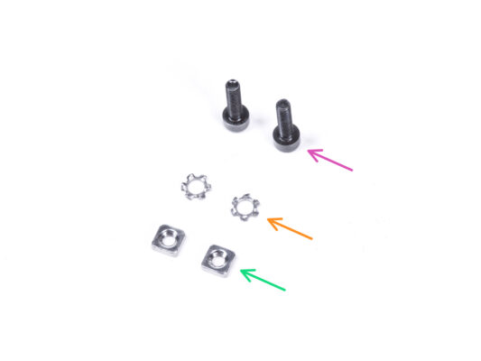
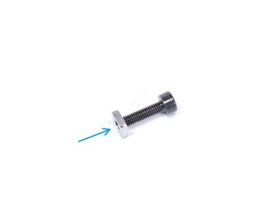
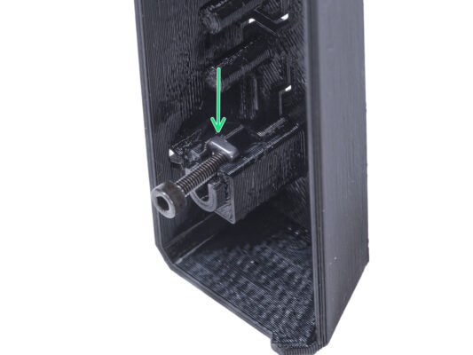
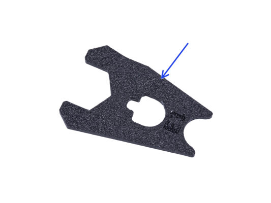
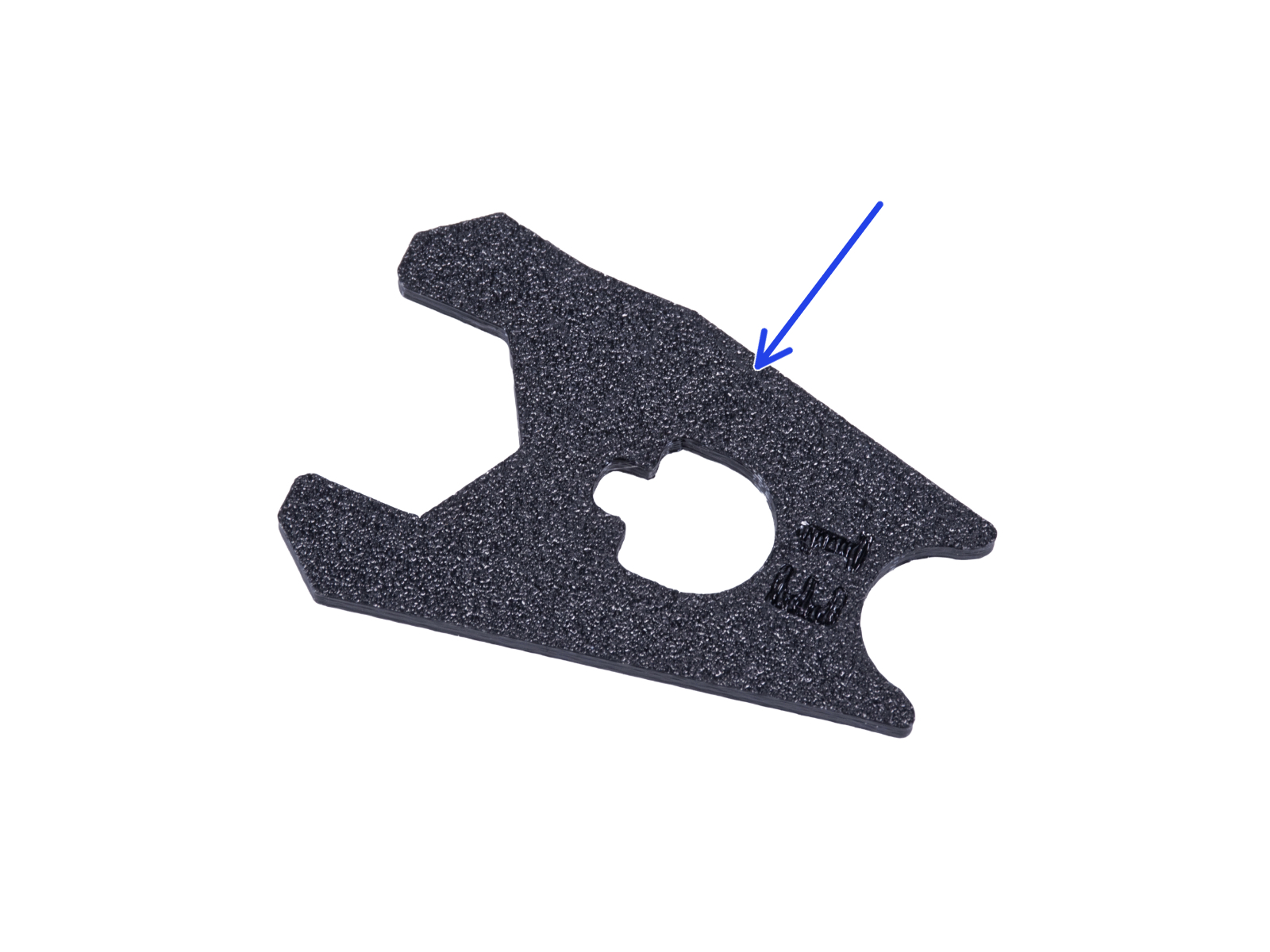
⬢Insérez l'écrou M3n dans chaque LED Stick Bracket.
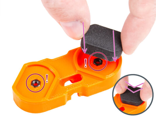
L'écrou doit être complètement encastré dans la pièce imprimée et au ras de la surface de la pièce. Un encastrement insuffisant de l'écrou peut entraîner des problèmes lors du montage dans l'enceinte.
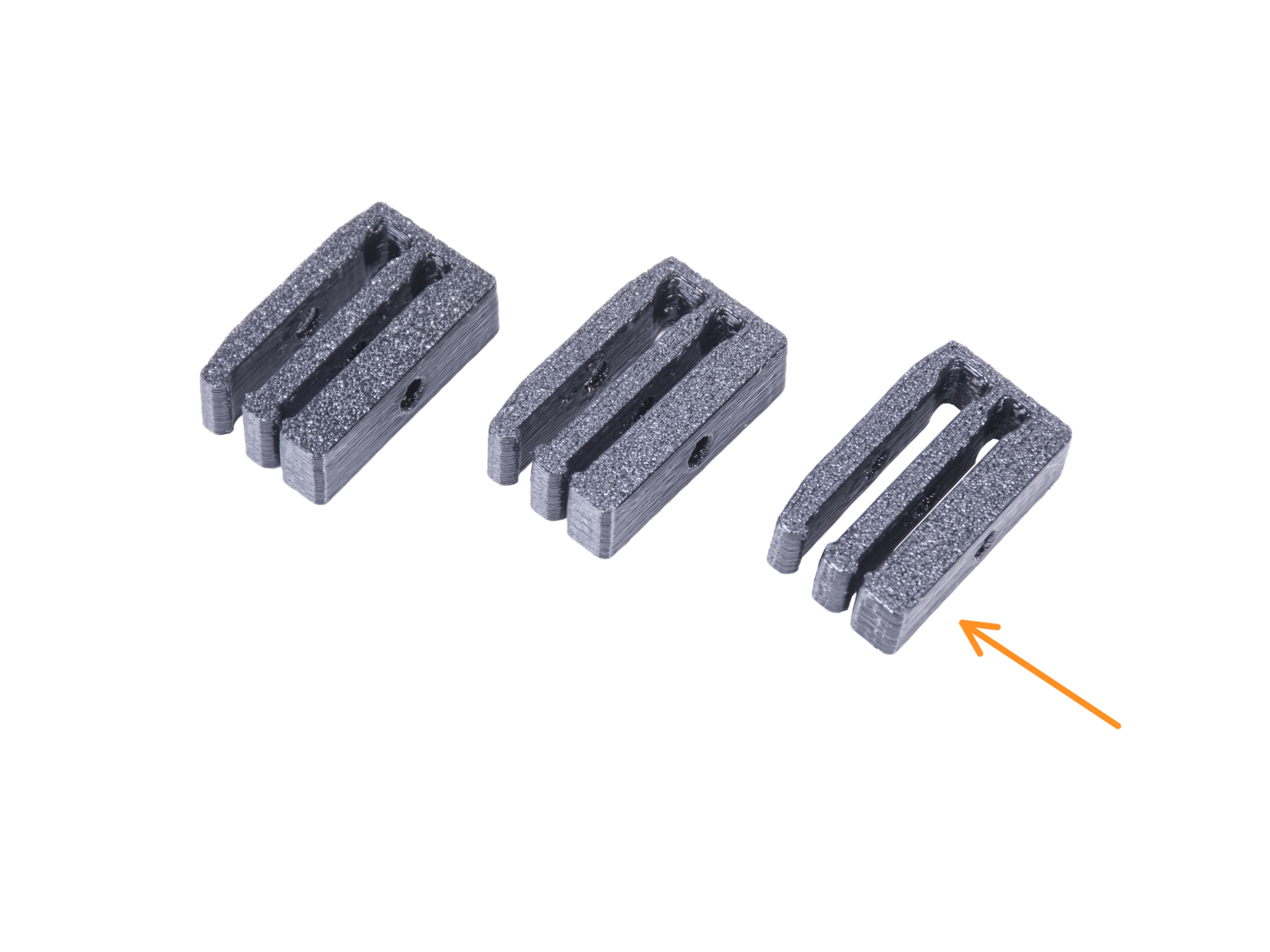
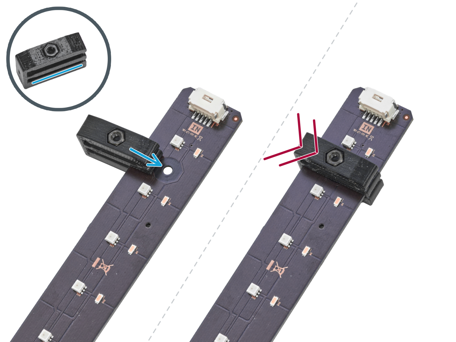
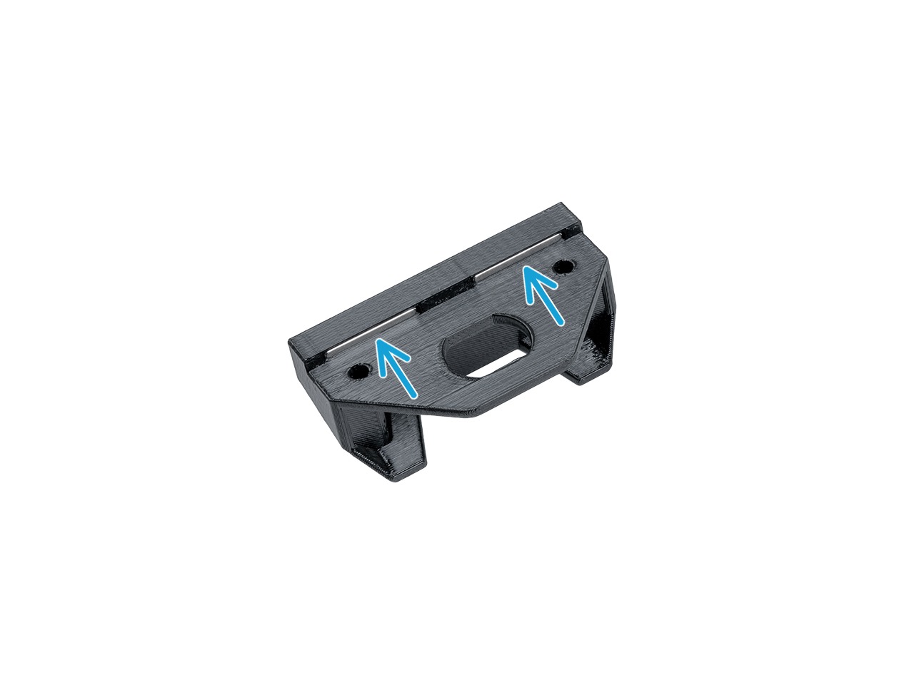
⬢Faites glisser la fente inférieure du LED Stick Bracket sur la LED Stick Board et alignez le bracket contre le premier trou de la LED Stick Board le plus proche du connecteur du LED Stick (blanc).
Évitez de faire glisser le support sur les puces et les diodes ! Cela peut les endommager définitivement.
⬢Poussez complètement le LED Stick Bracket sur la LED Stick Board.
⬢Utilisez cette procédure pour les trois LED Stick Brackets.
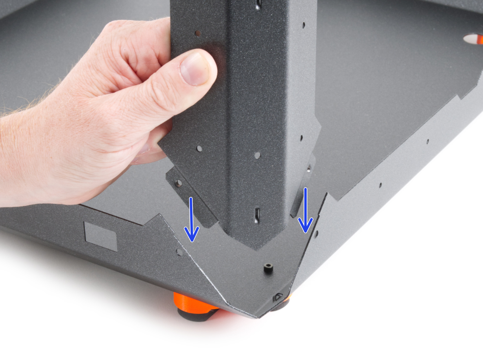
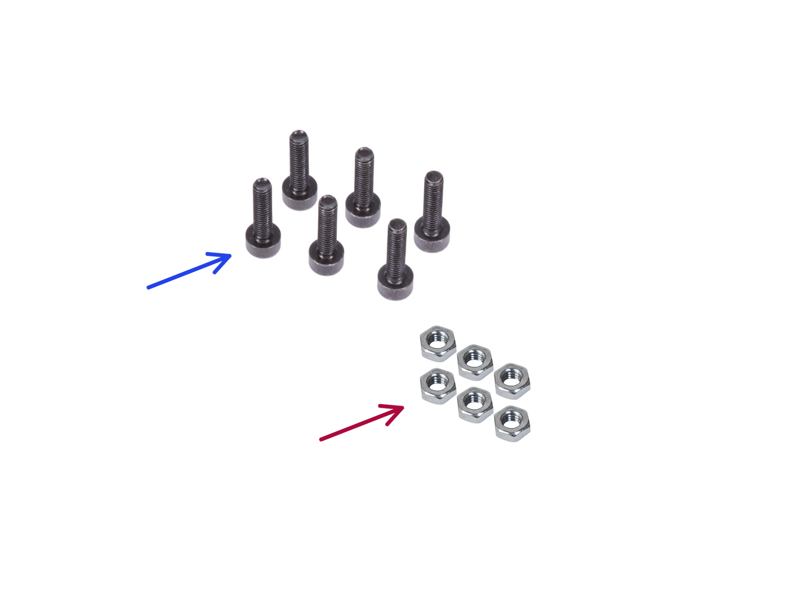
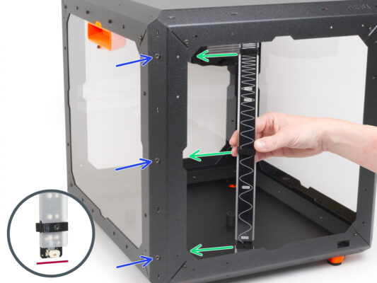
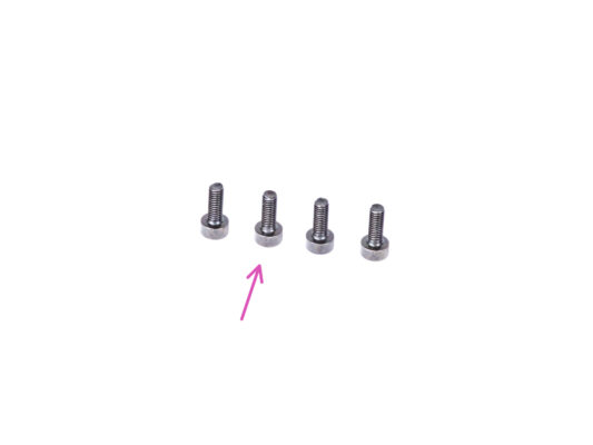
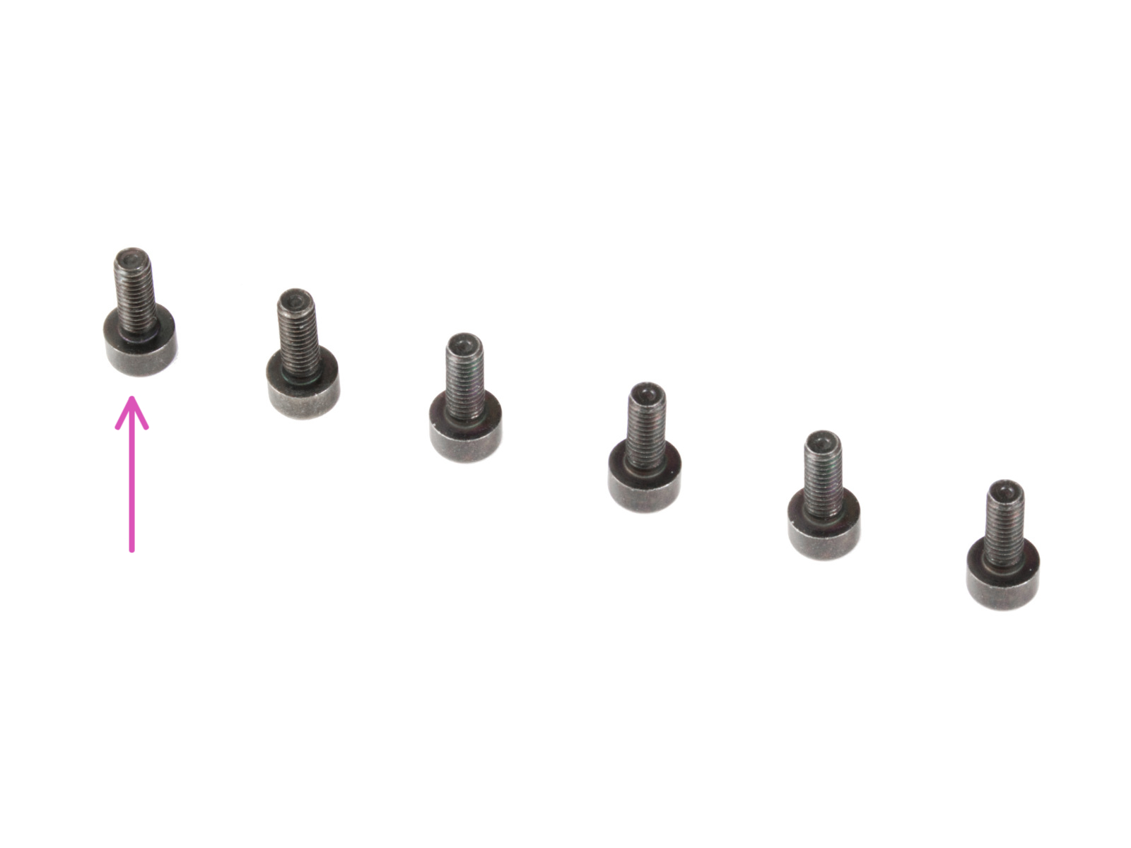
⬢De l'extérieur, insérez trois vis M3x18 dans les trous du profilé de support avant gauche.
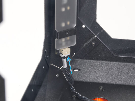
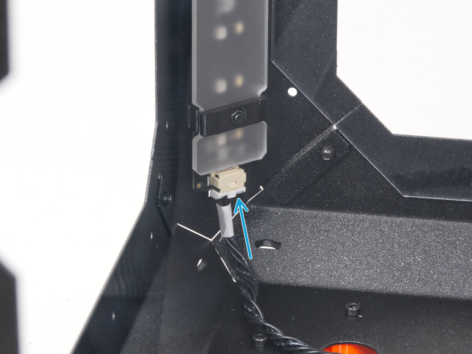
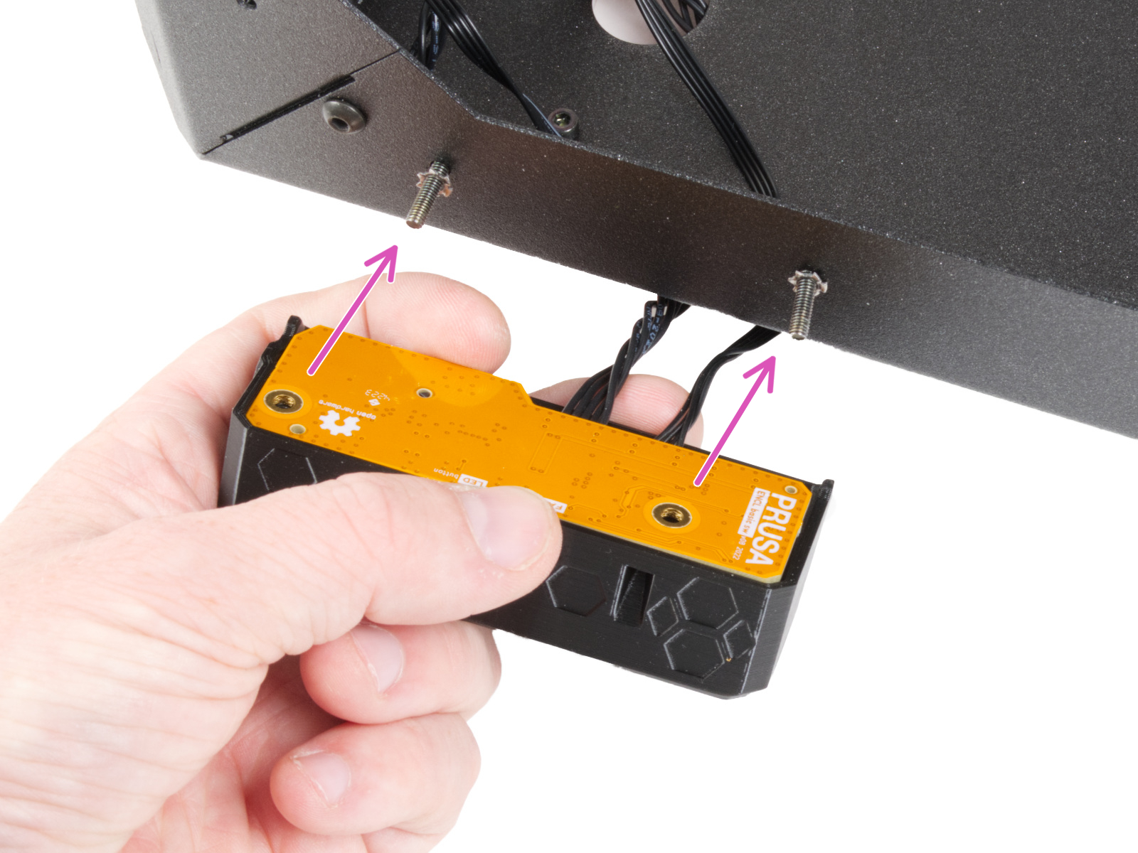
⬢From the inside of the enclosure, attach the LED strip assembly so that the LED stick brackets are aligned precisely with the screws. Attach the back side (the side without the diffuser).
Make sure, the LED connector is facing down.
⬢Once the LED strip is aligned, attach it by tightening all three inserted M3x18 screws. Tighten them firmly but gently.
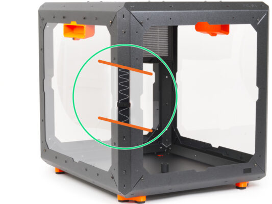
If you have only the White LED Strip add-on, skip this step.
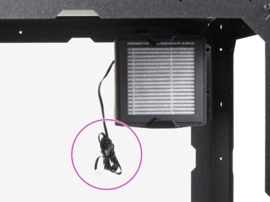
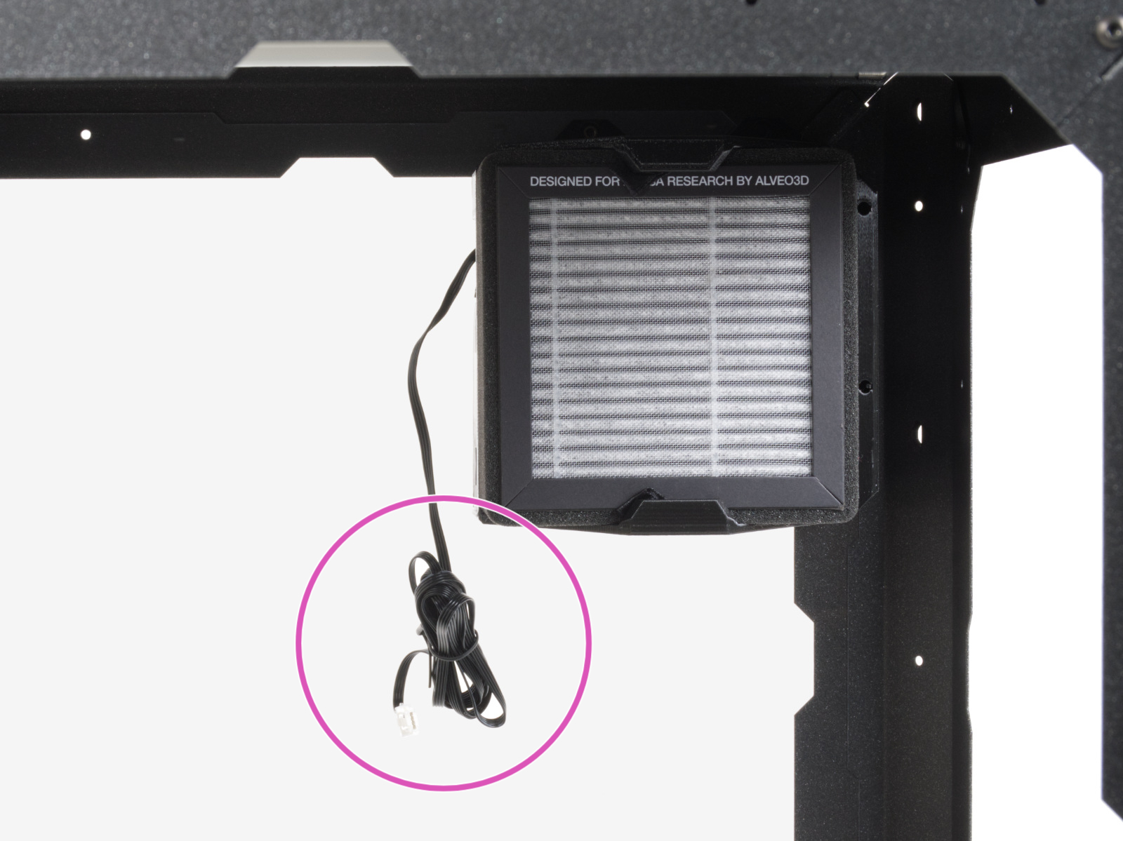
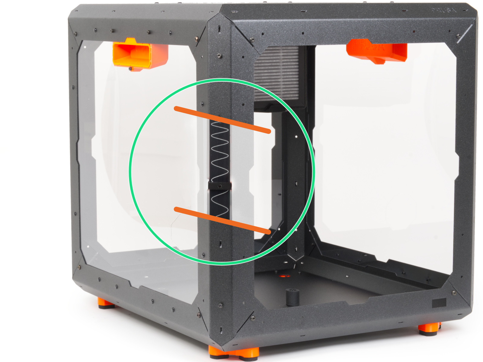
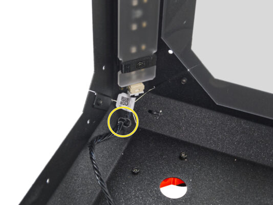
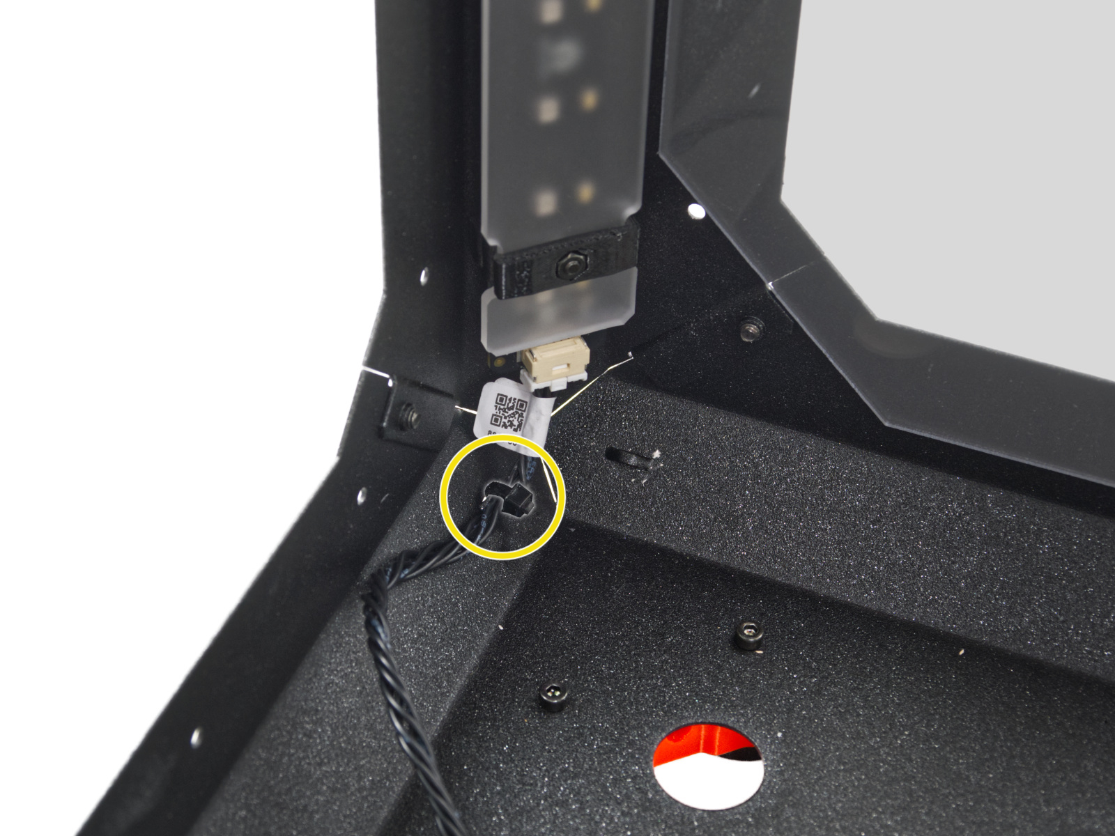
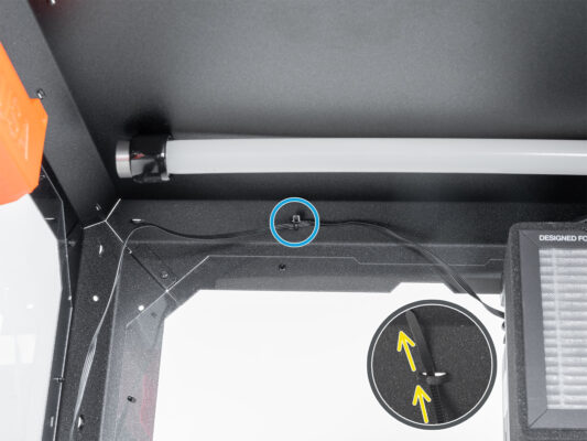
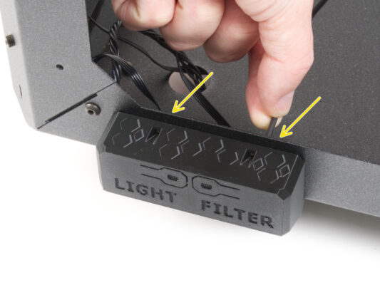
⬢Guide the zip tie thought the perforation in the top panel near the filtration.
⬢Using this zip tie, secure the filtration cable. Do not overtighten the zip tie, as it may cause fatal damage to the cable.
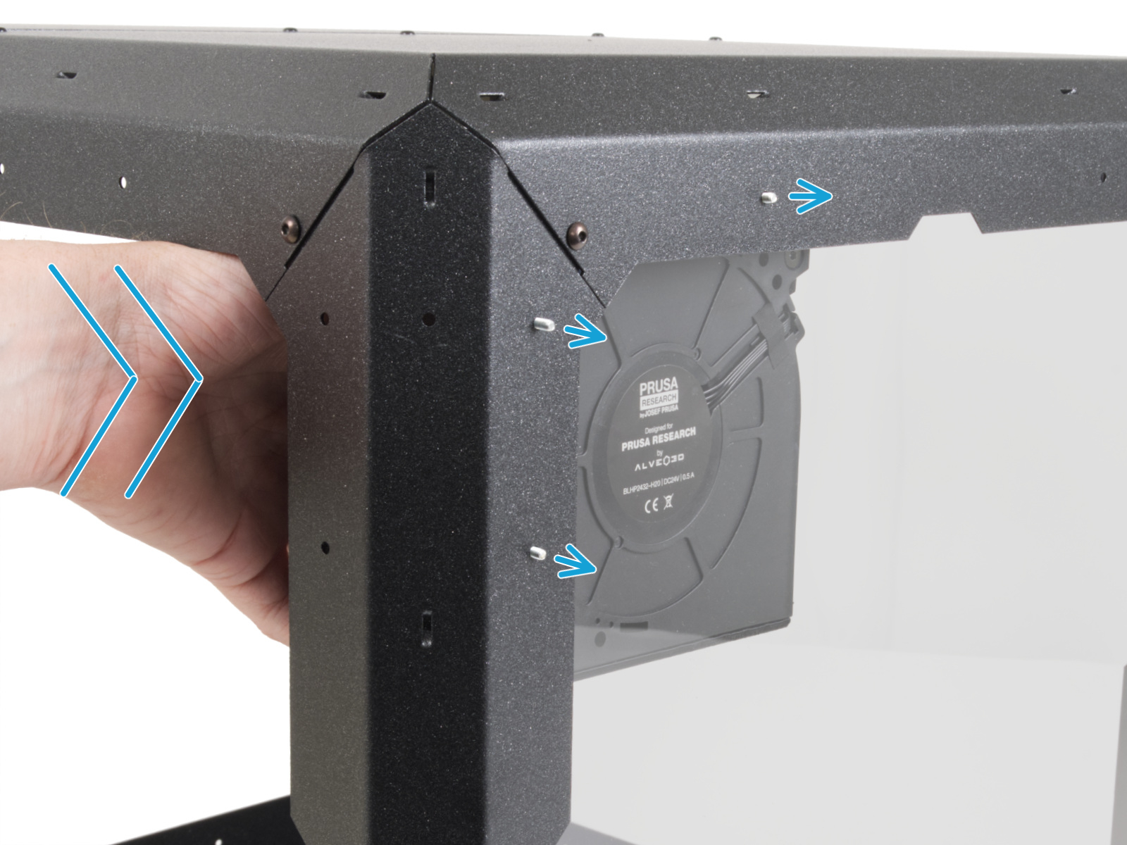
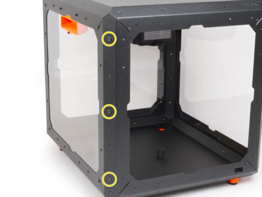
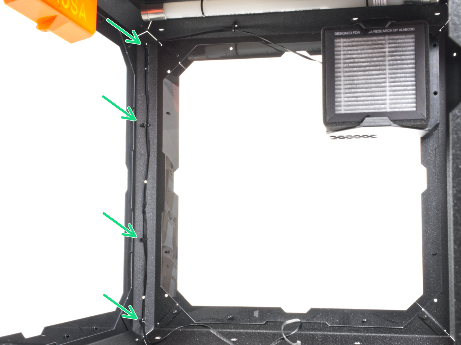
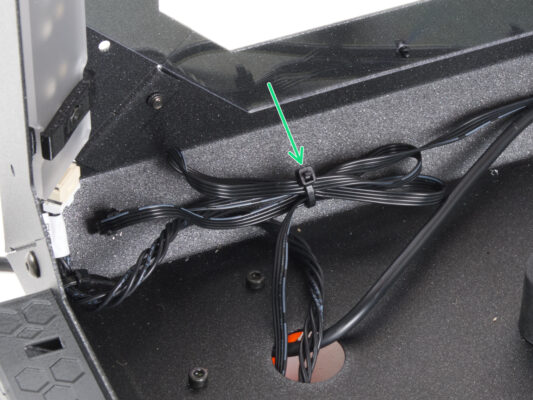
⬢In the same way, secure the cable to the four perforations in the left rear profile. Do not overtighten the zip ties, as it may cause fatal damage to the cable.
Exercise caution when handling anything inside the enclosure. There are sharp metal plates, so avoid injury.
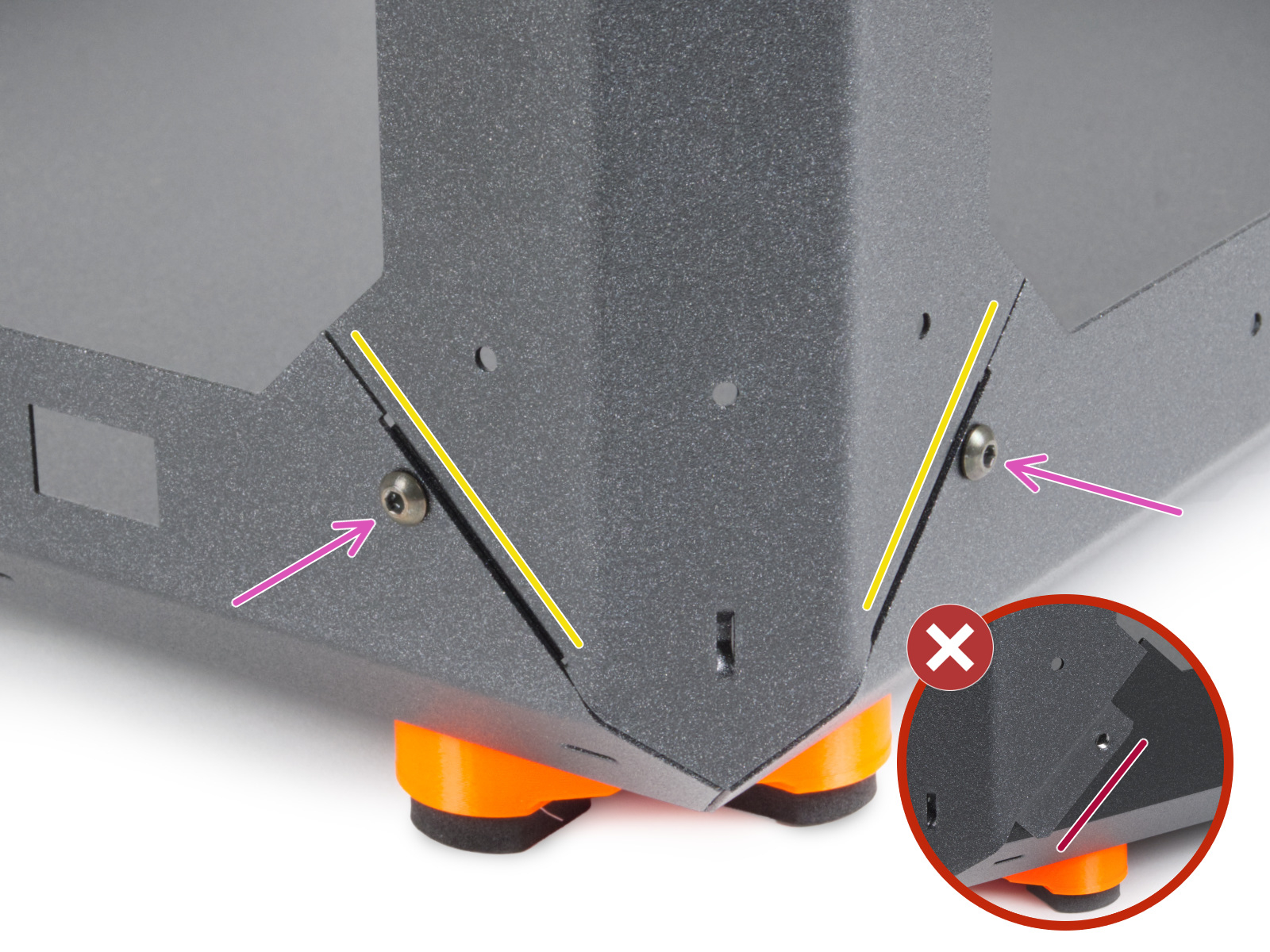
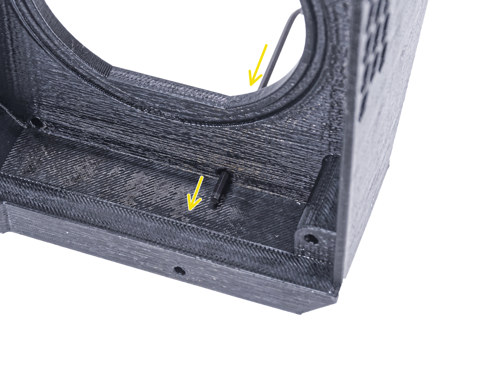
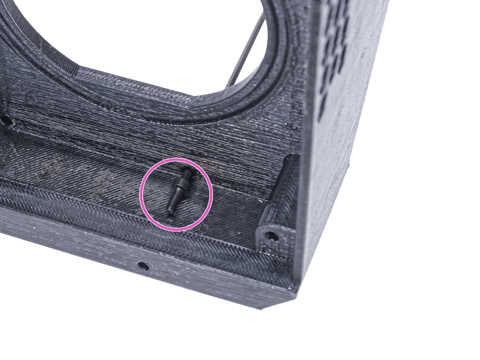
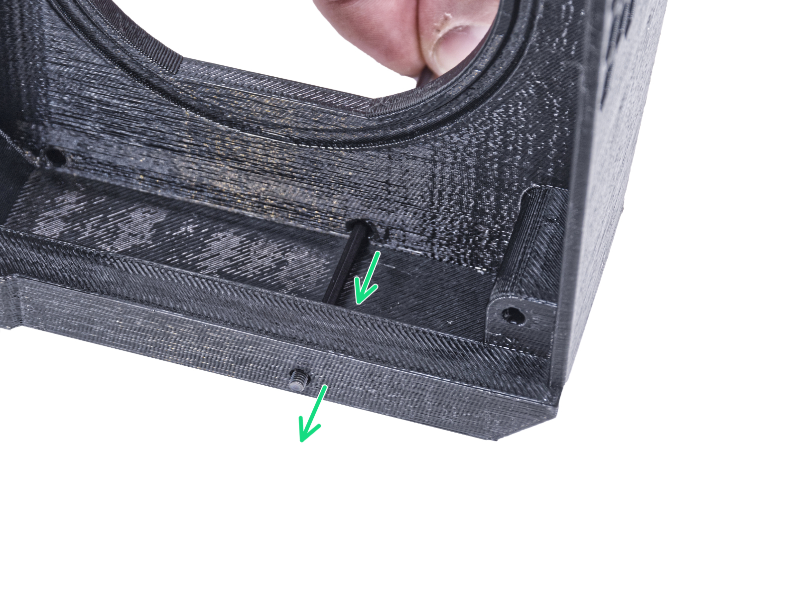
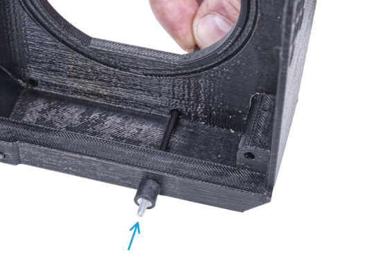
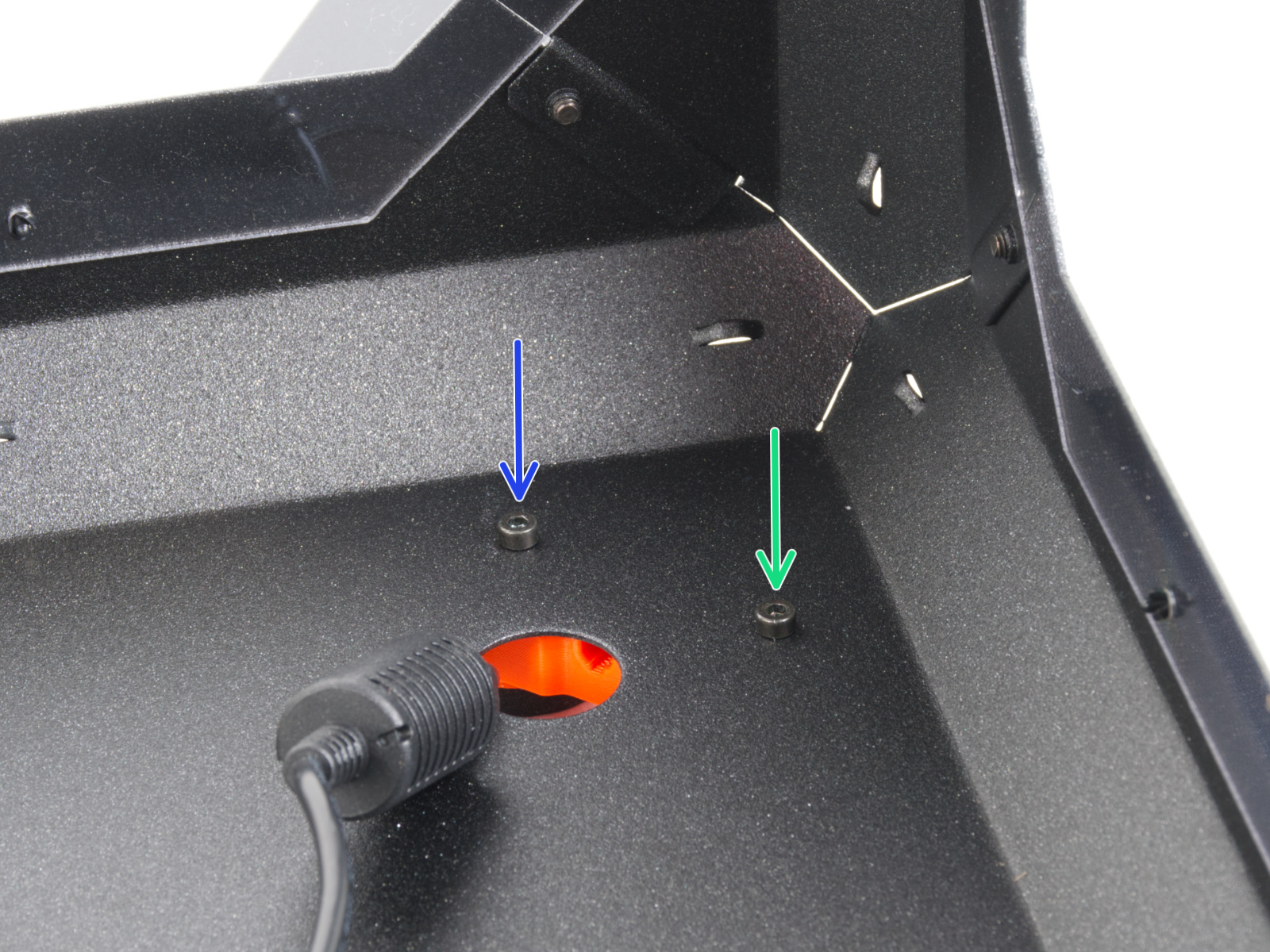
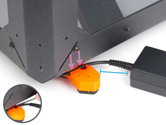
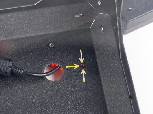
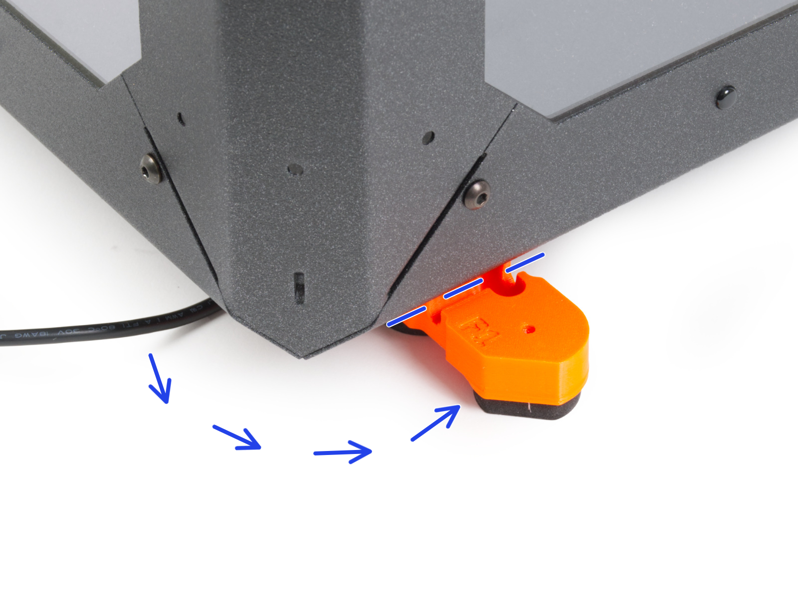
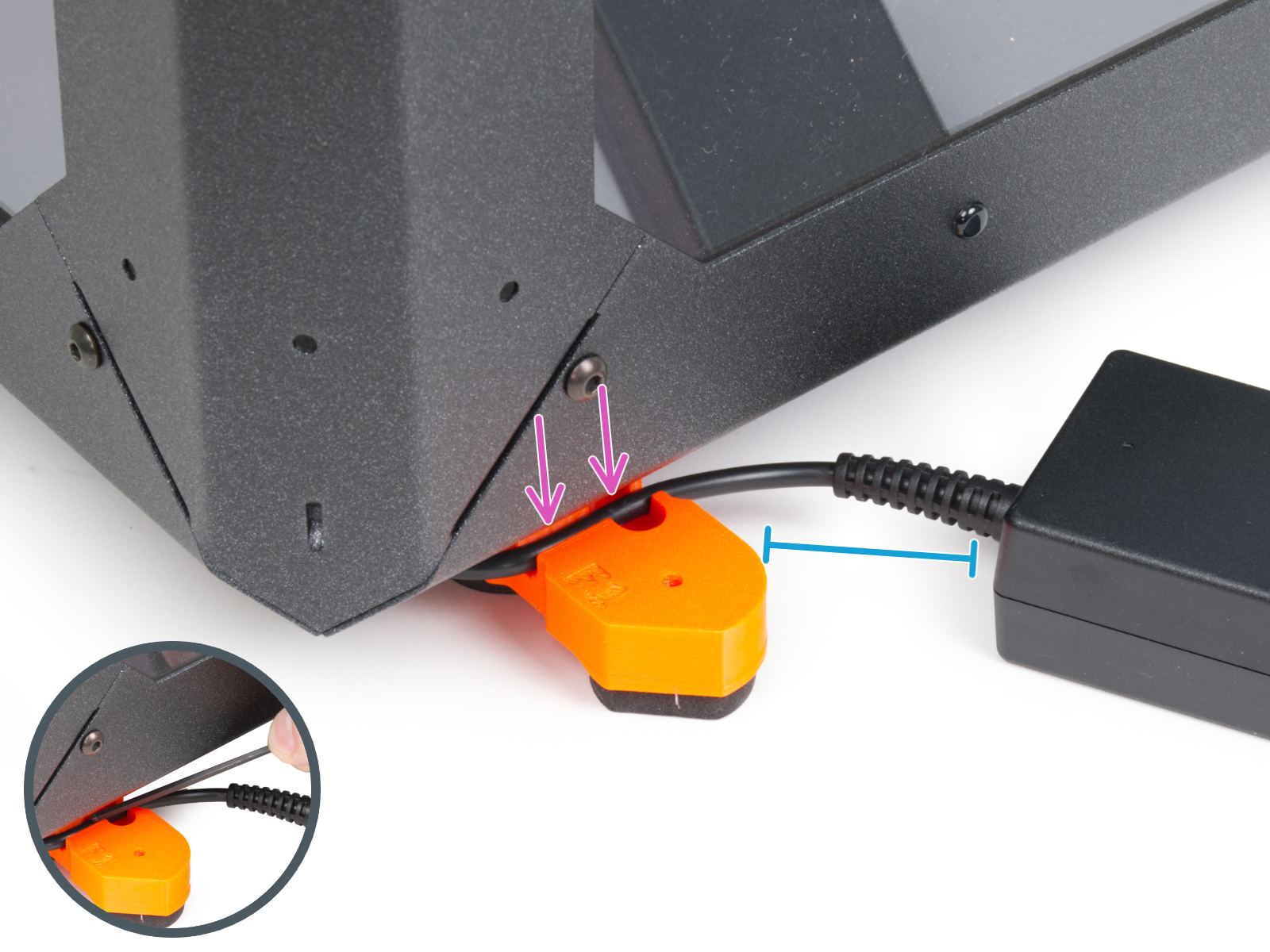
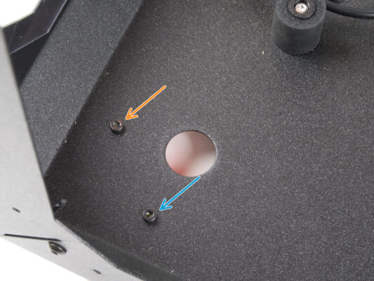
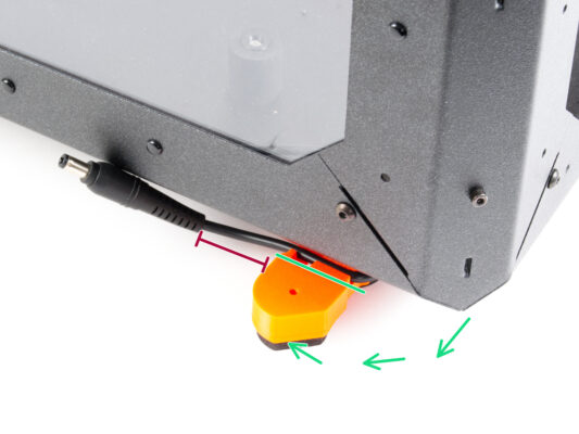
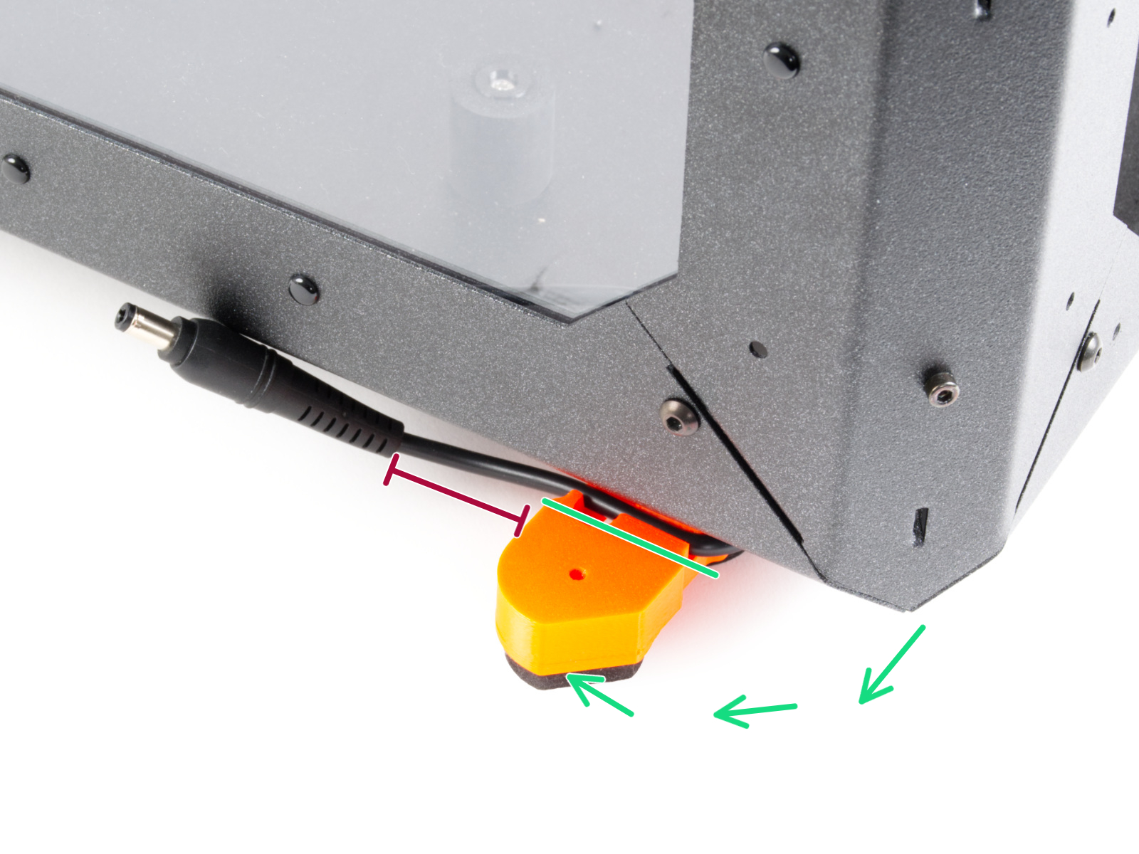
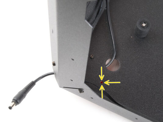
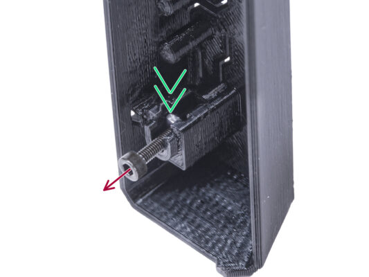
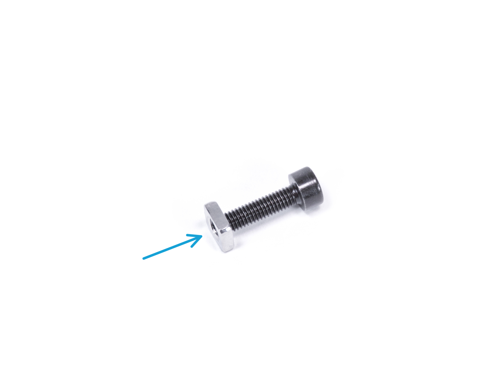
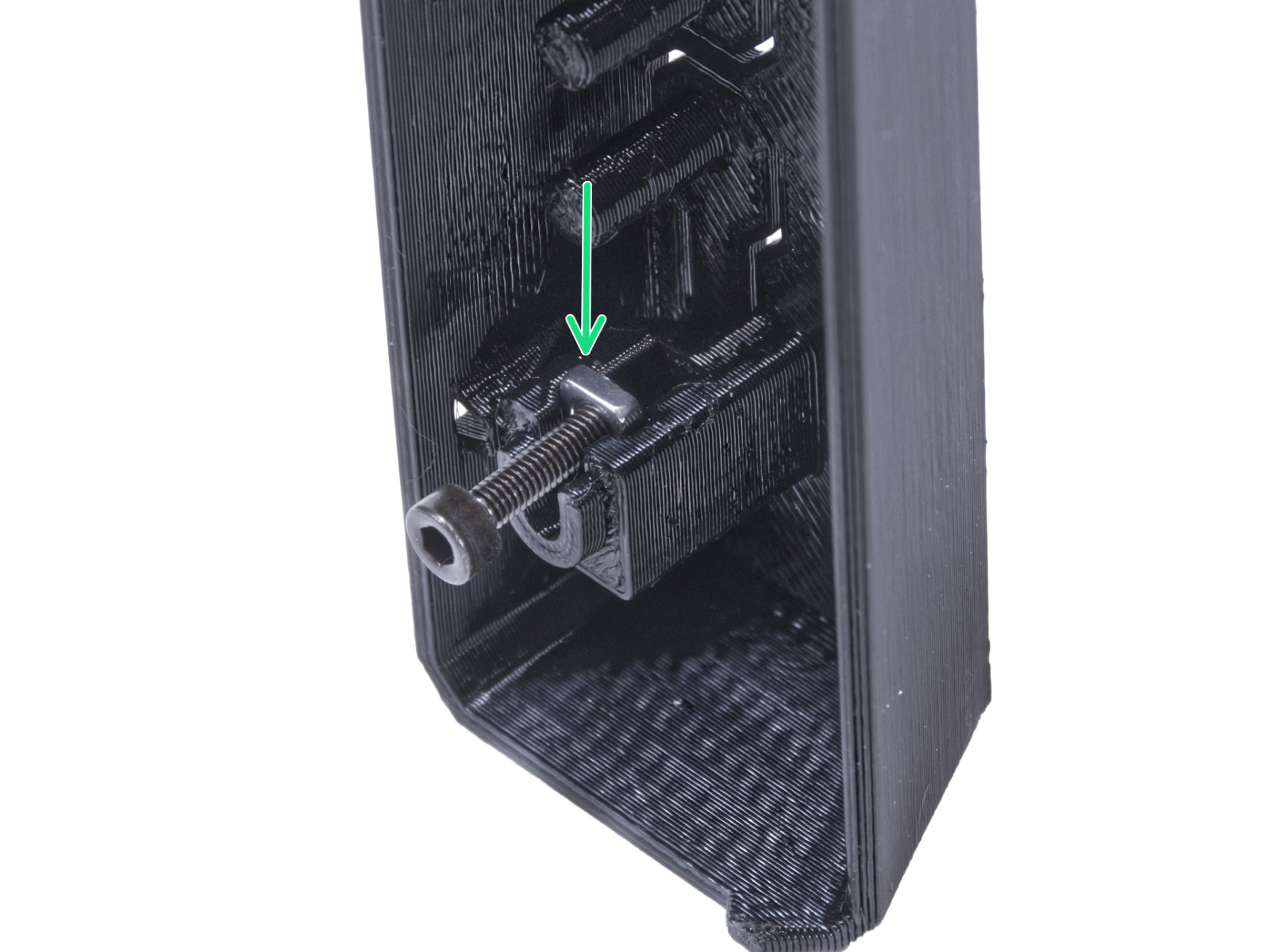
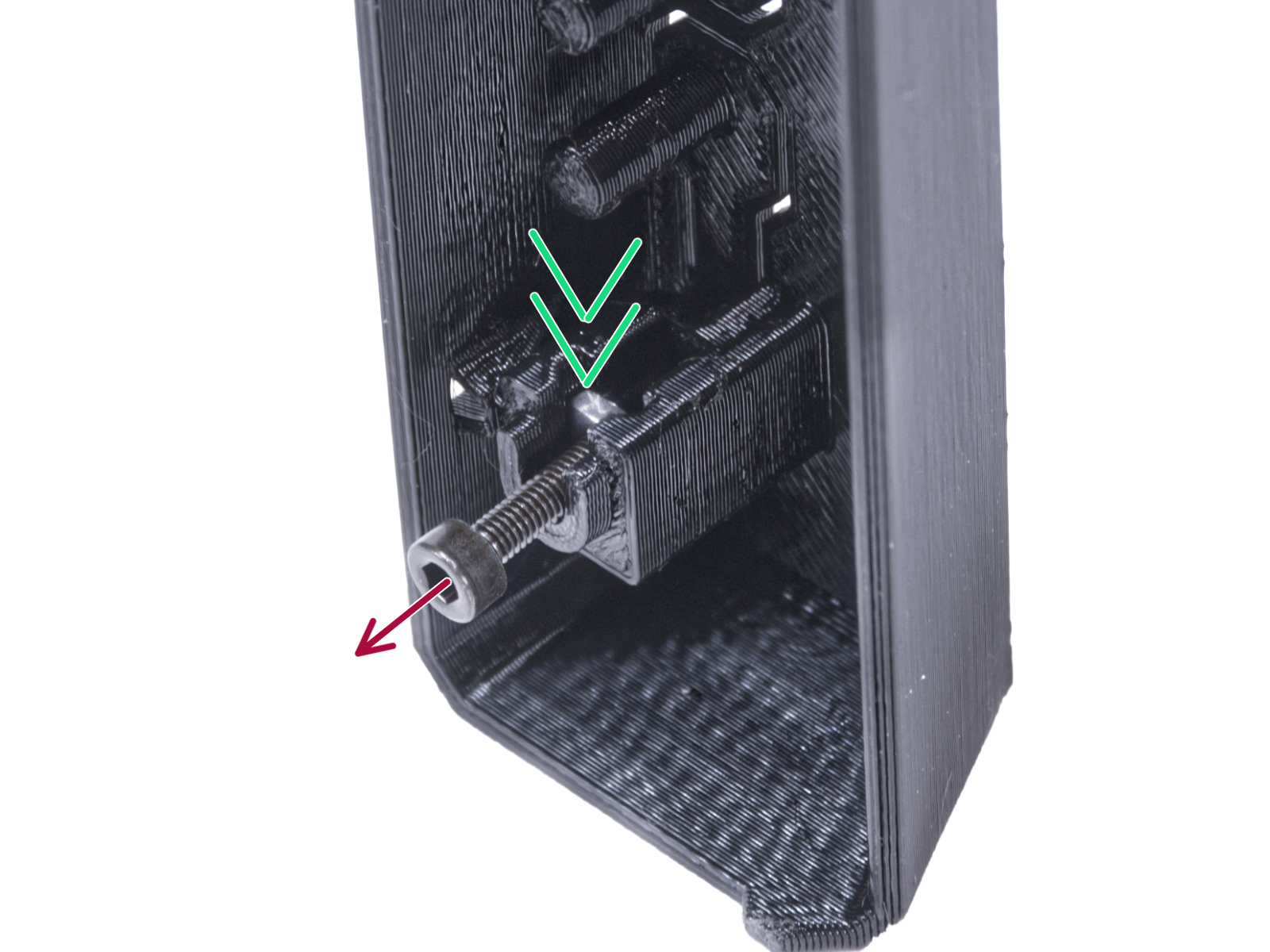
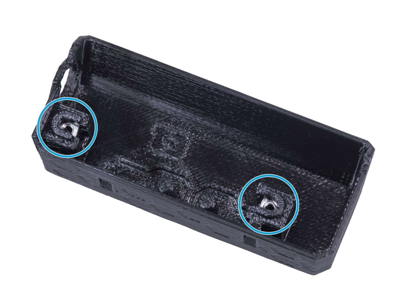
⬢After aligning the hole, secure the foot by inserting back the M3x12 screw.
⬢Fully tighten the left screw.
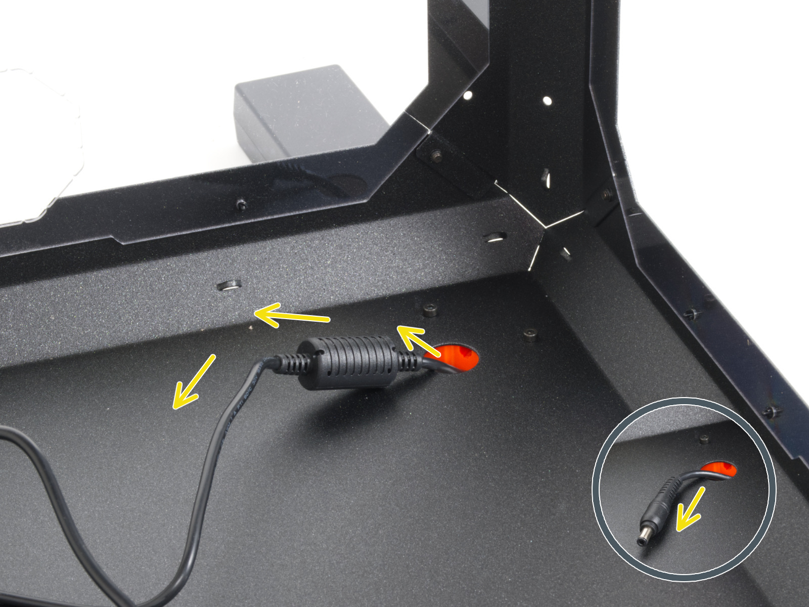
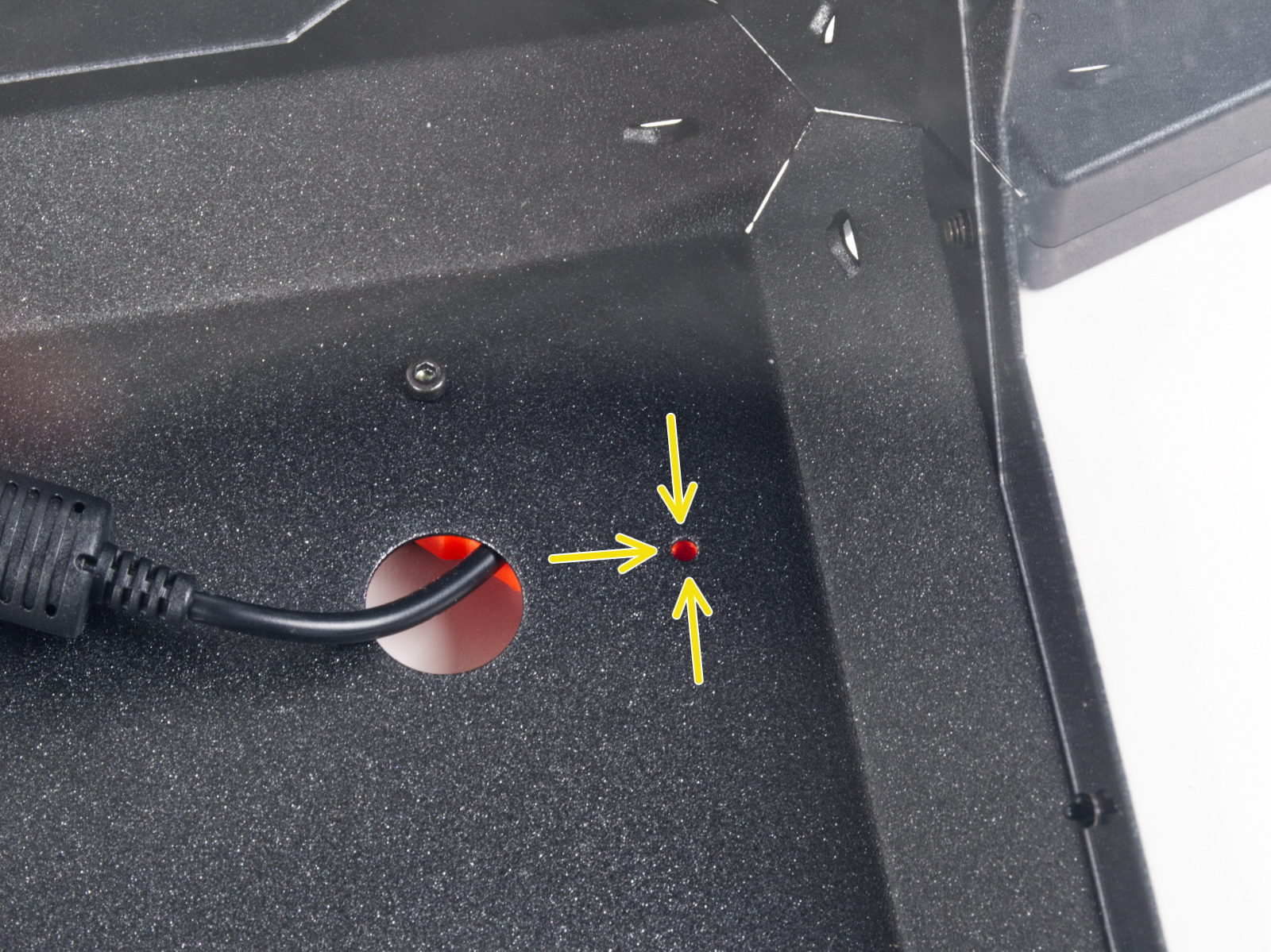
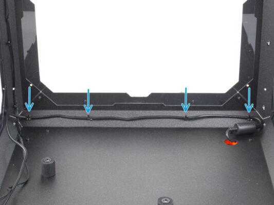
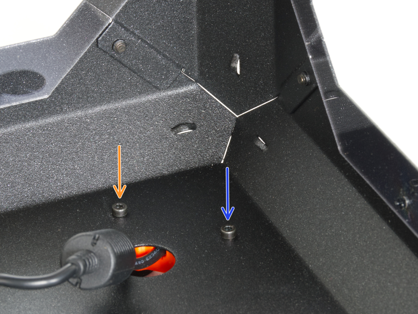
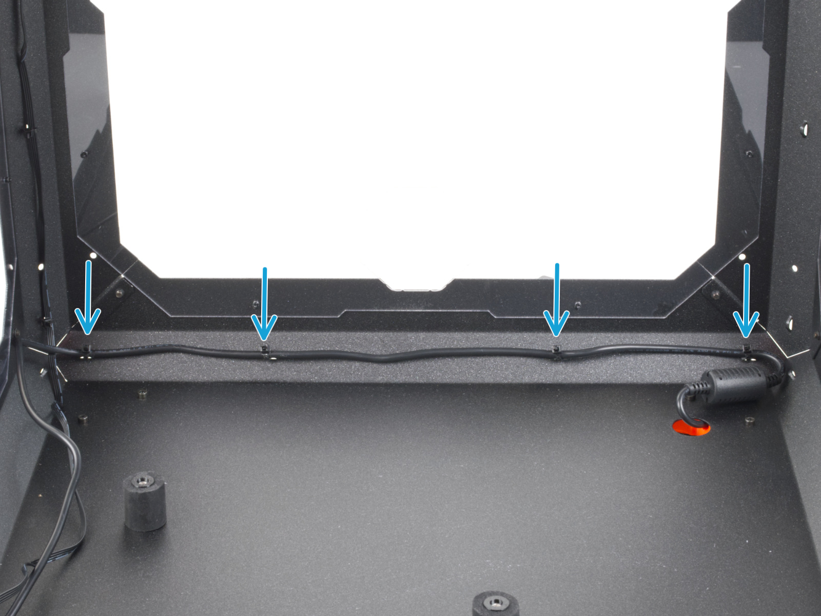
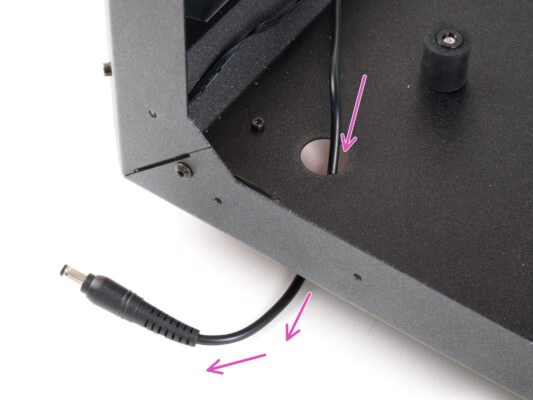
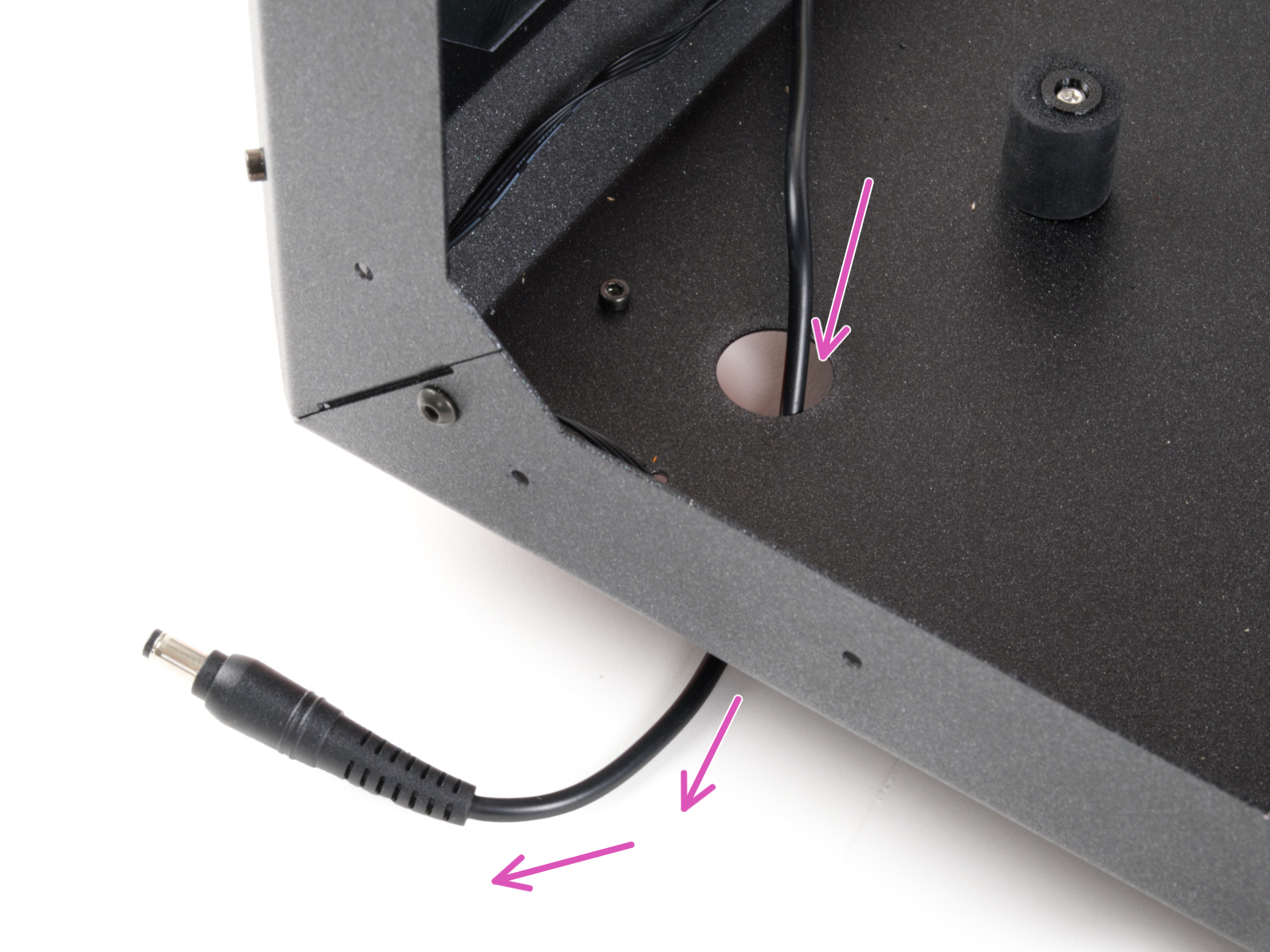
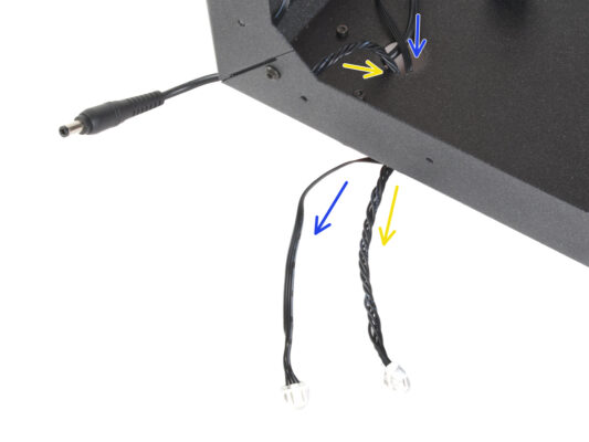
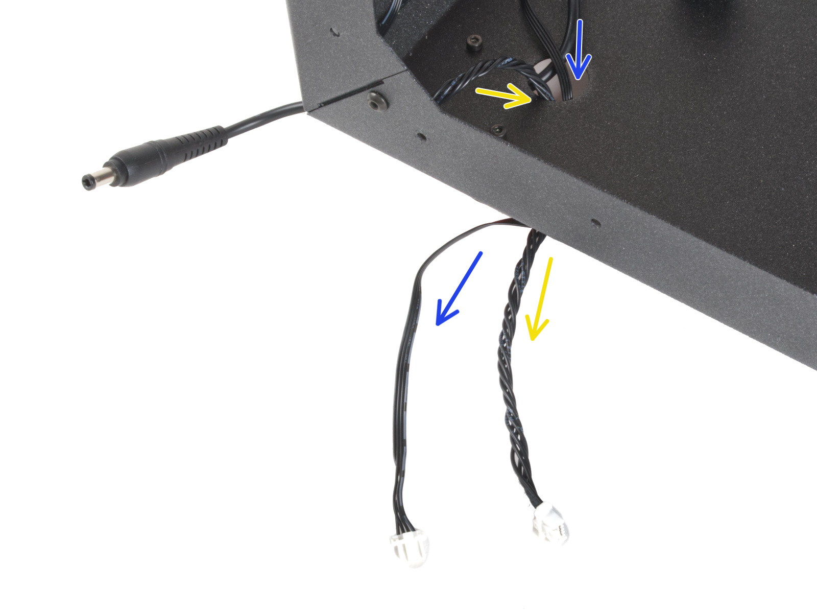
⬢Guide the cable along the rear side of the Enclosure and secure it using four zip ties through the perforations. Do not overtighten the zip ties, you can damage the cable.
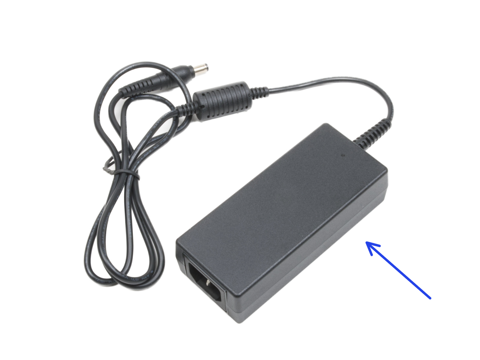
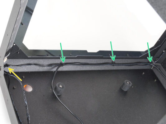
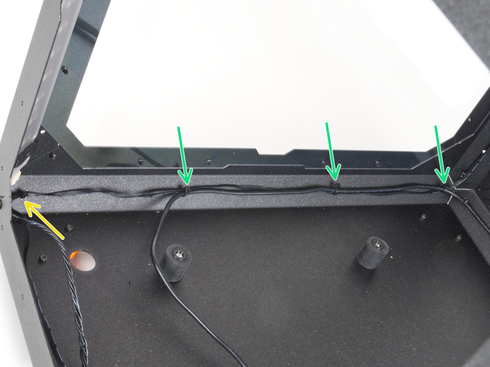
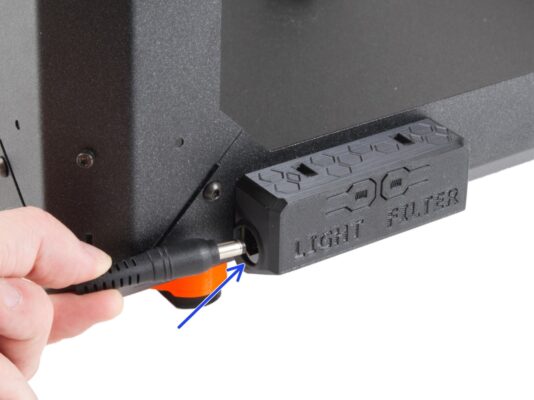
⬢Guide the PSU cable along the left side of the Enclosure and secure it with the three zip ties.
⬢If you have installed the Advanced Filtration System, guide the filtration cable together with the PSU cable. And secure it with one extra zip tie in the left corner.
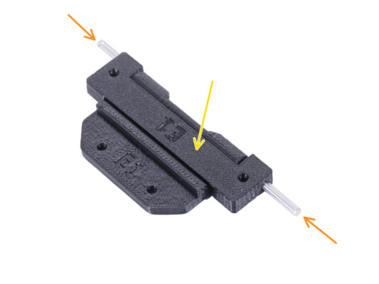
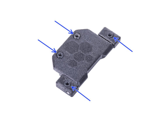
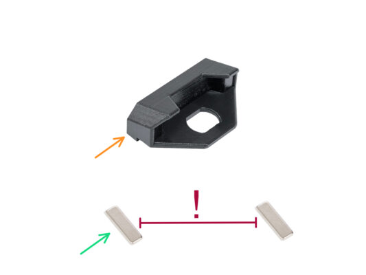
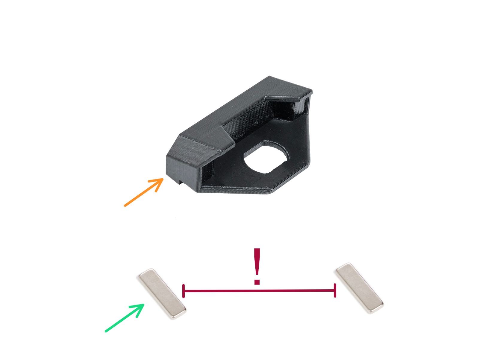
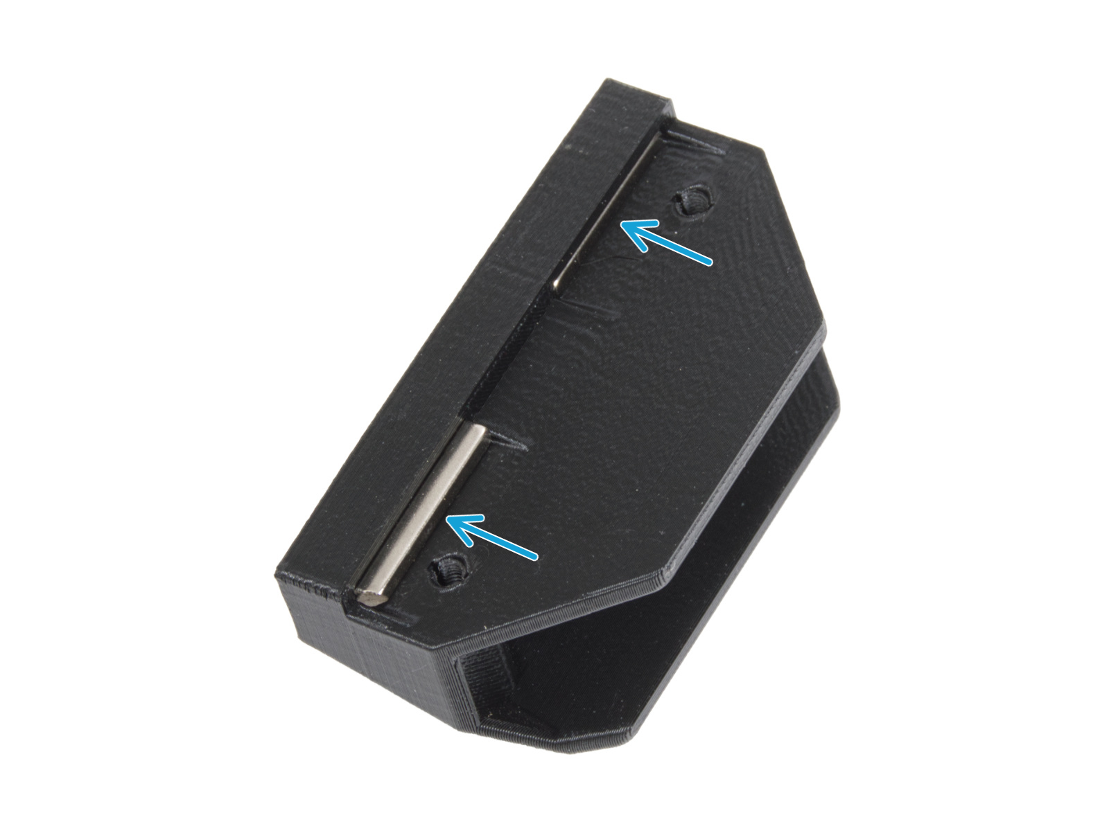
⬢Placez la charnière de l'enceinte dans la charnière de la porte. Voir la bonne orientation des deux pièces.
Regardez attentivement l'orientation des deux pièces. Leur démontage inverse est impossible.
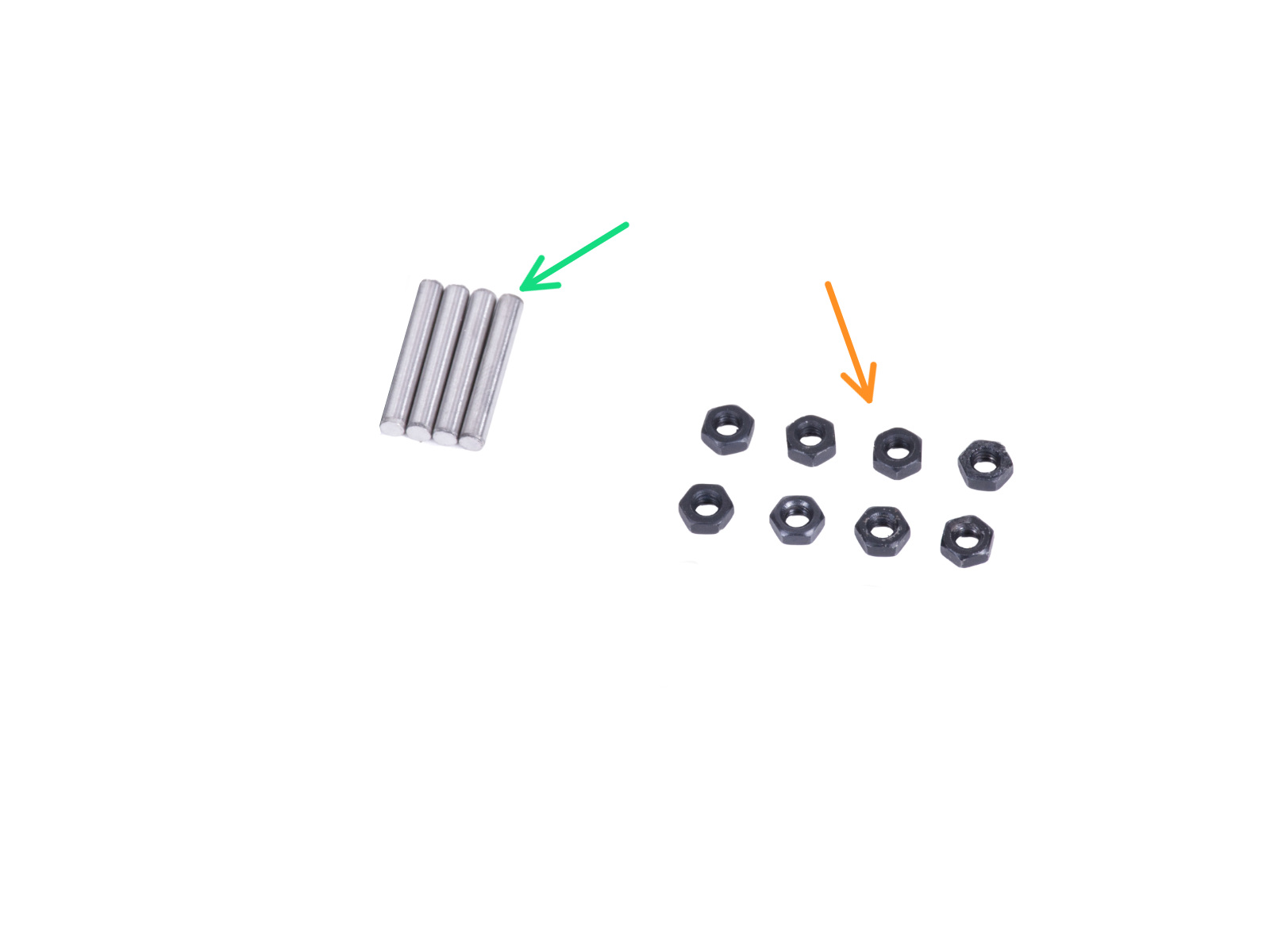
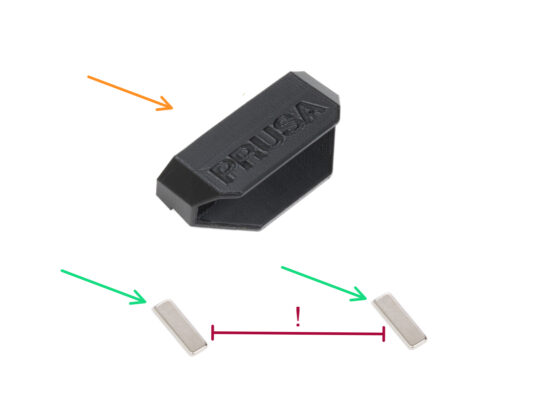
⬢Insérez la goupille des deux côtés de la charnière.
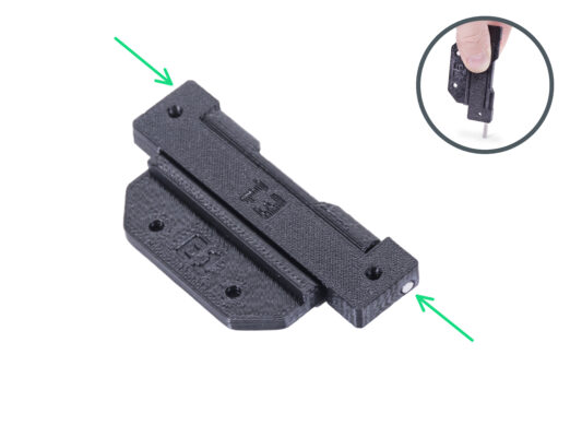
⬢Poussez deux goupilles à fond dans la charnière contre une surface dure (par exemple une table d'atelier). L'extrémité de la goupille doit être alignée avec la surface de la pièce imprimée.
In the following instructions, we will install the hinges on the left side. However, it is optional which side you install the hinges on. The procedure is identical and does not affect the later installation of the door.
⬢Retournez l'enceinte avec la face avant face à vous.
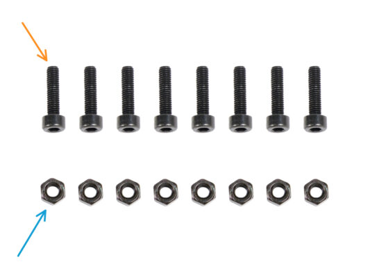
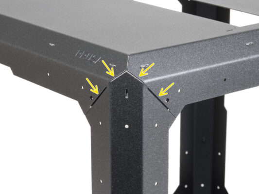
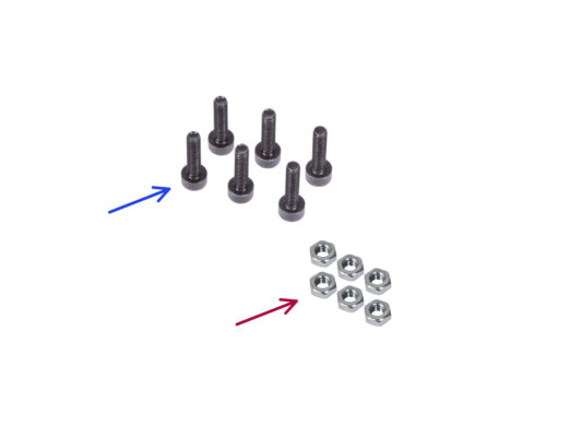
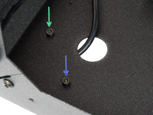
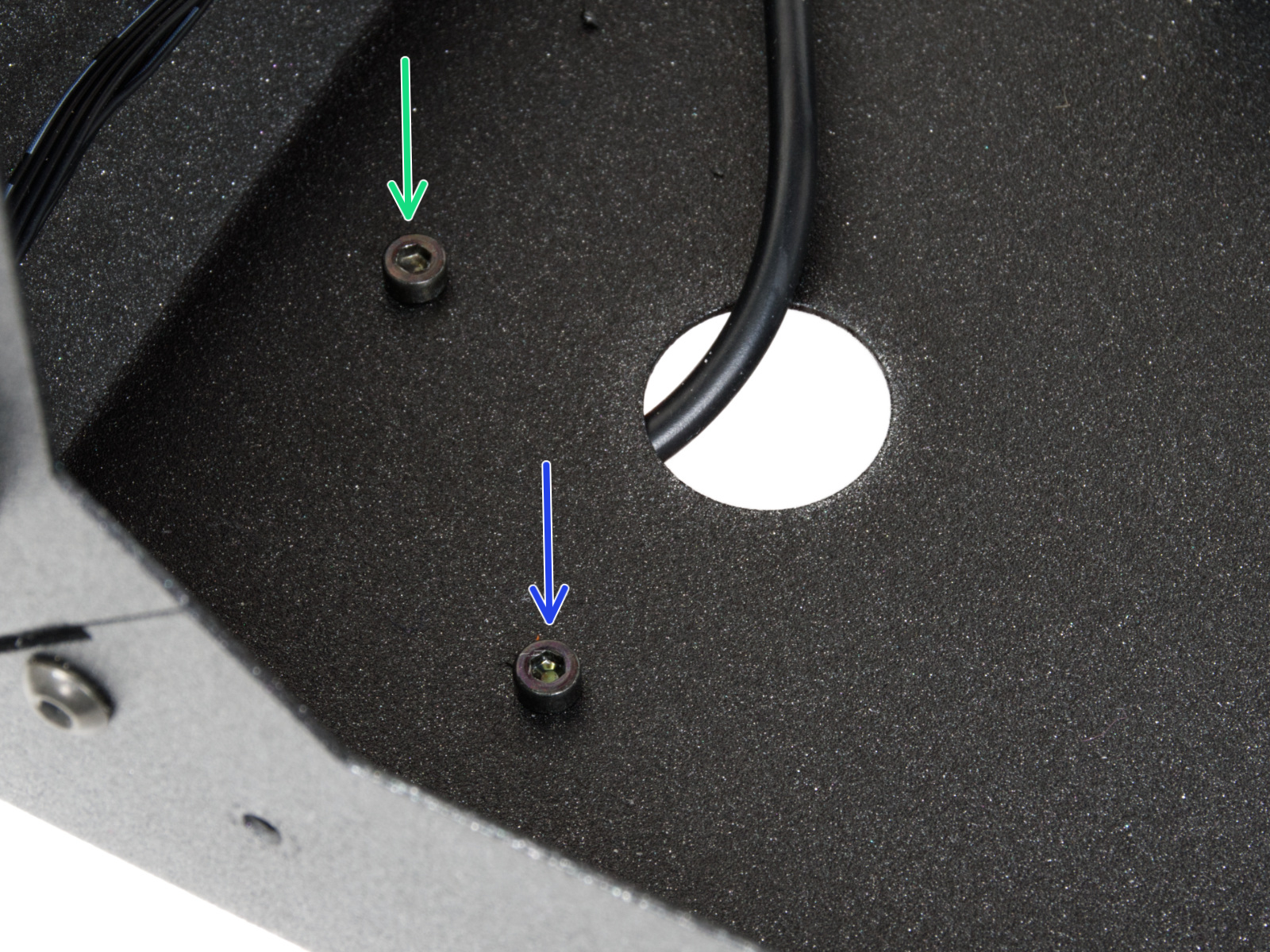
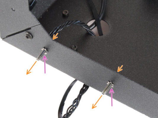
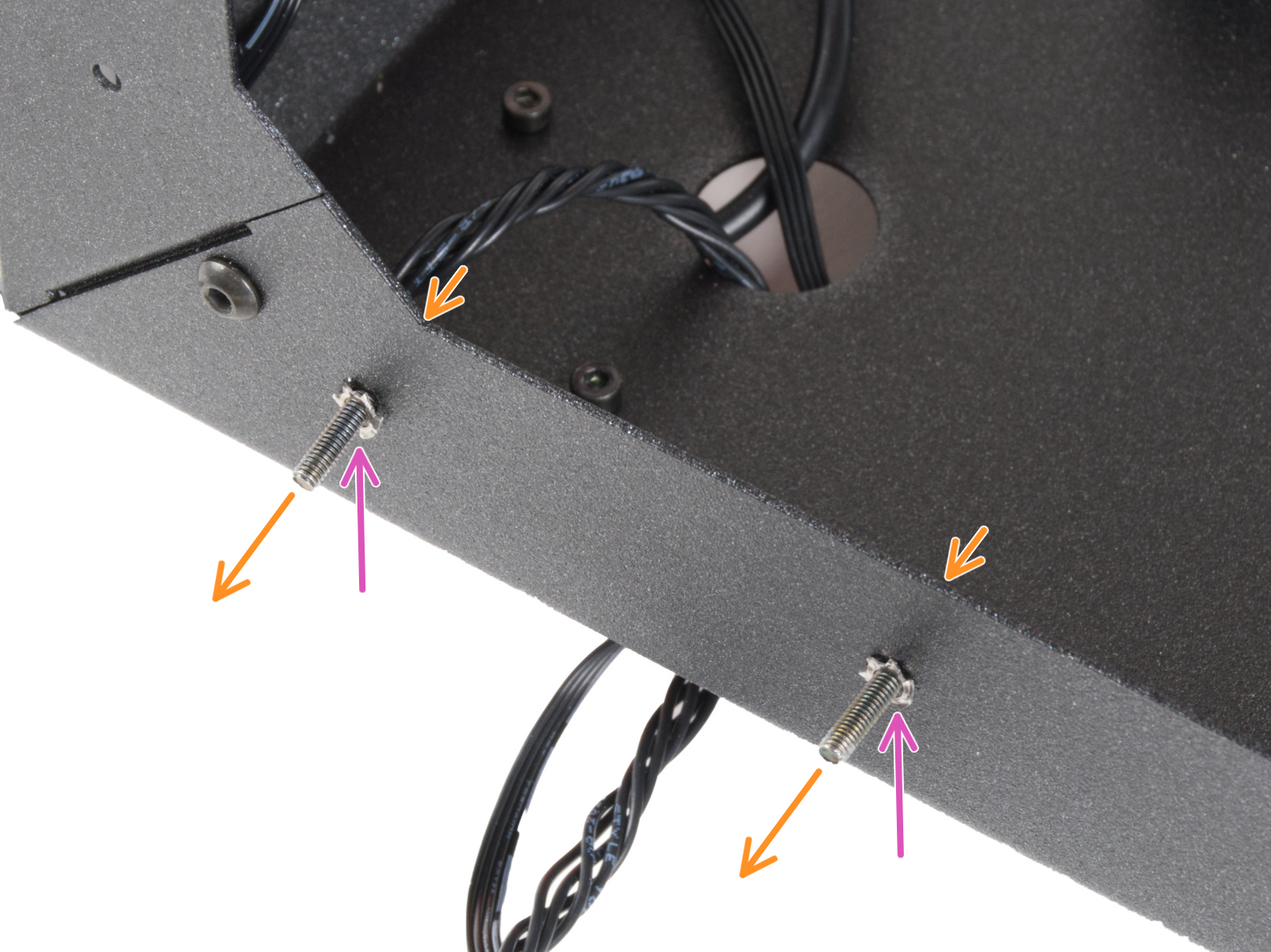
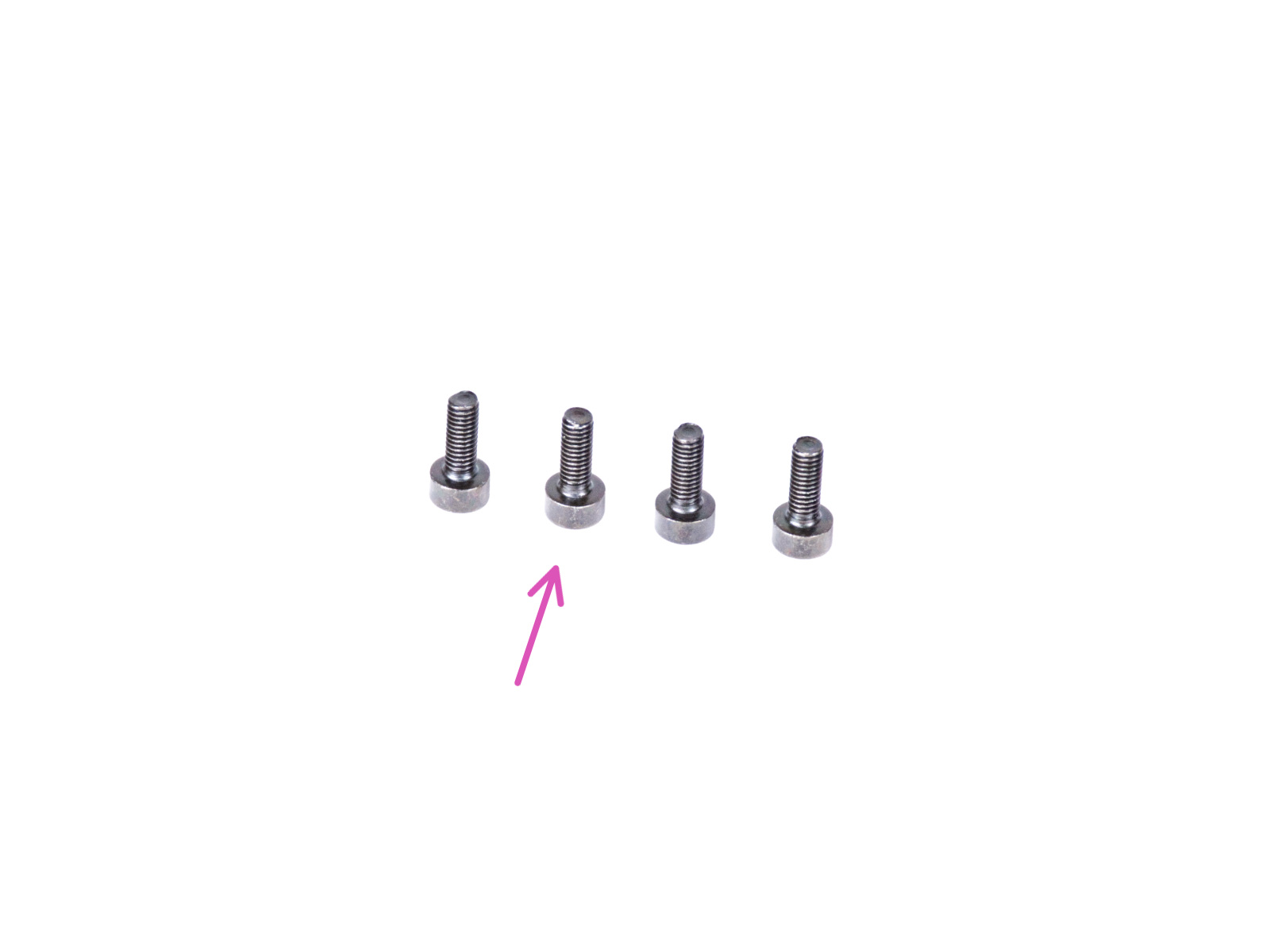
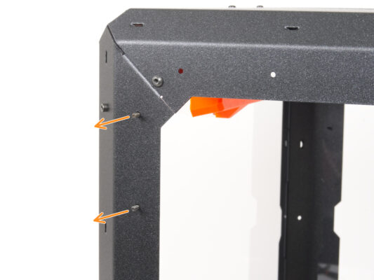
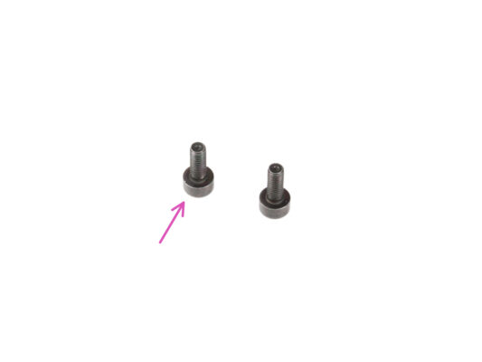
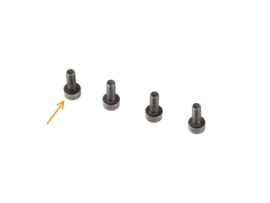
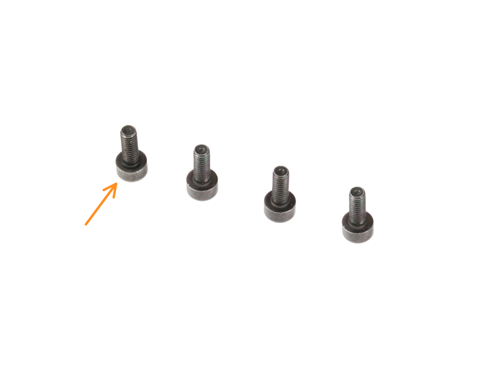
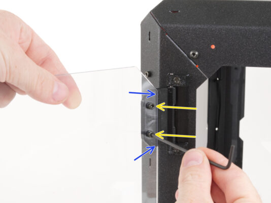
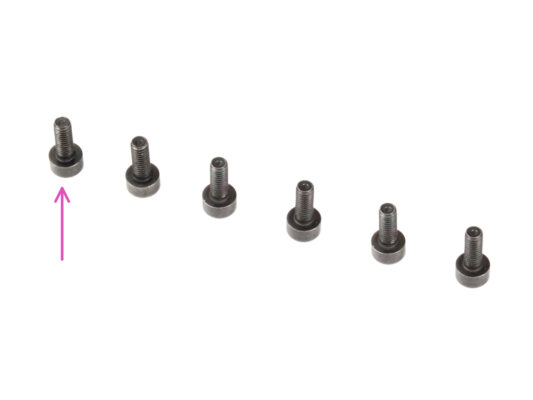
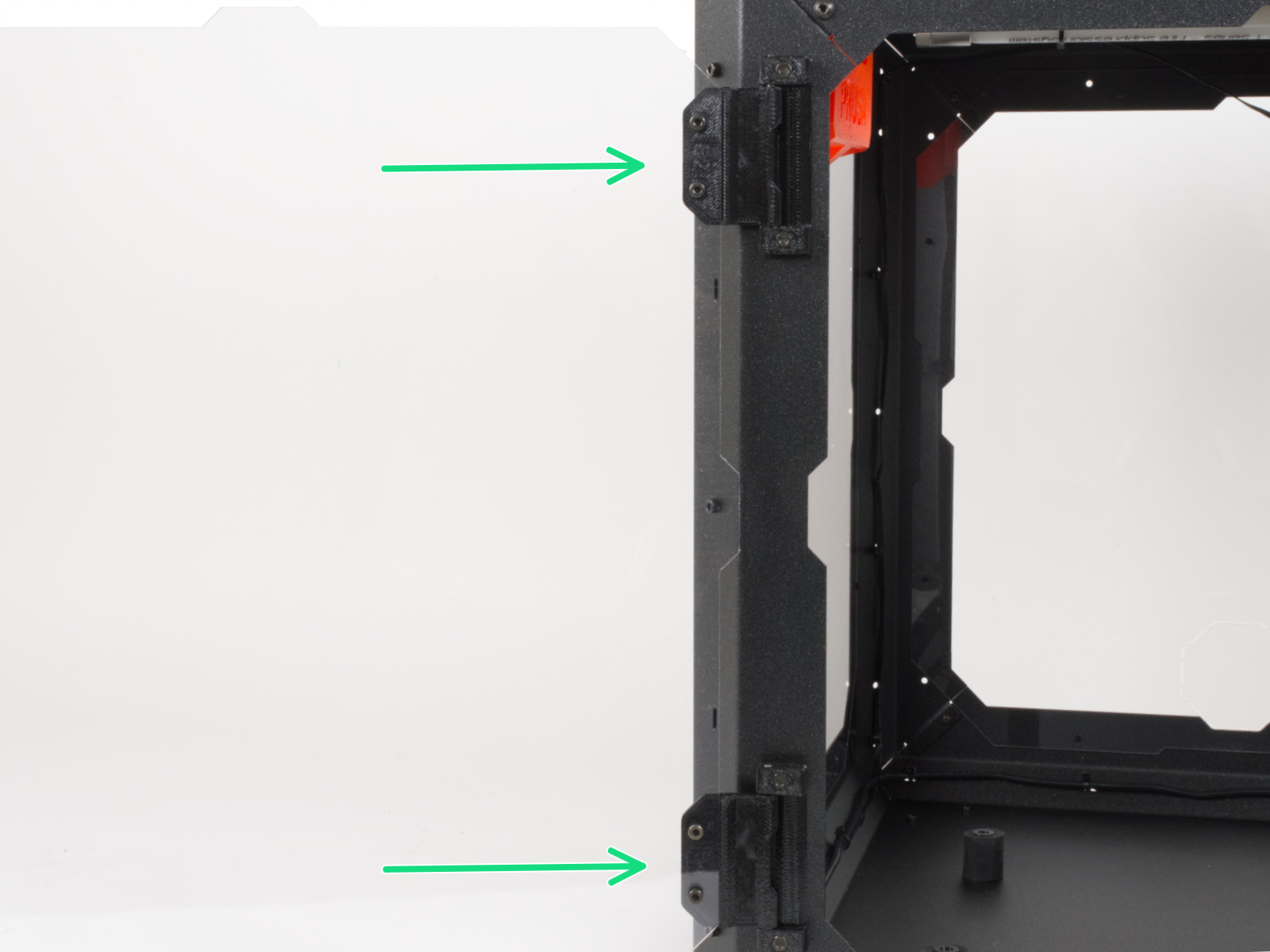
⬢Locate two holes on the top of the left support. From the inside, insert two M3x8 screws.
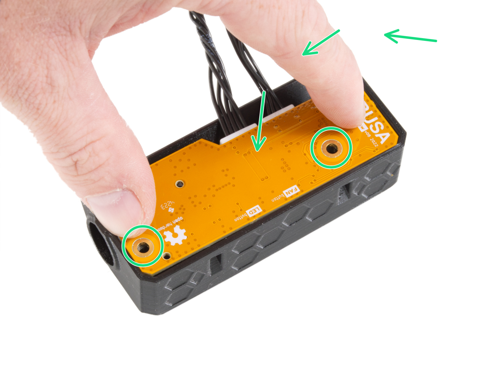
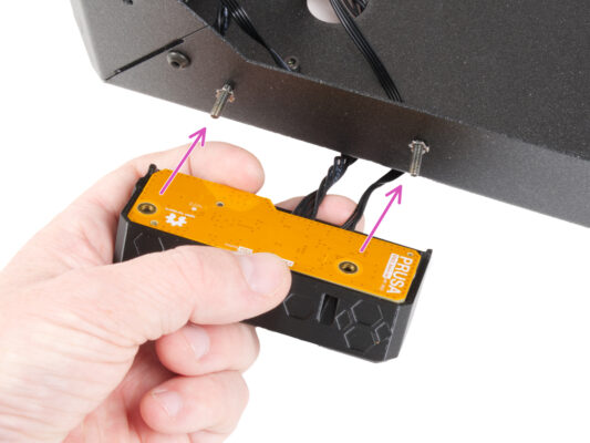
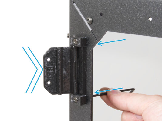
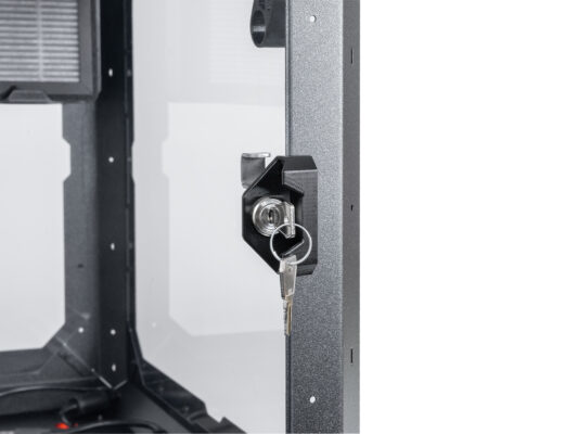
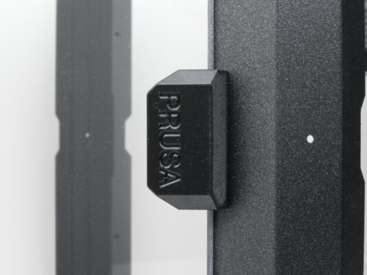
⬢Attach the hinge on the screws and tighten the screws. Mind the correct orientation of the hinge.
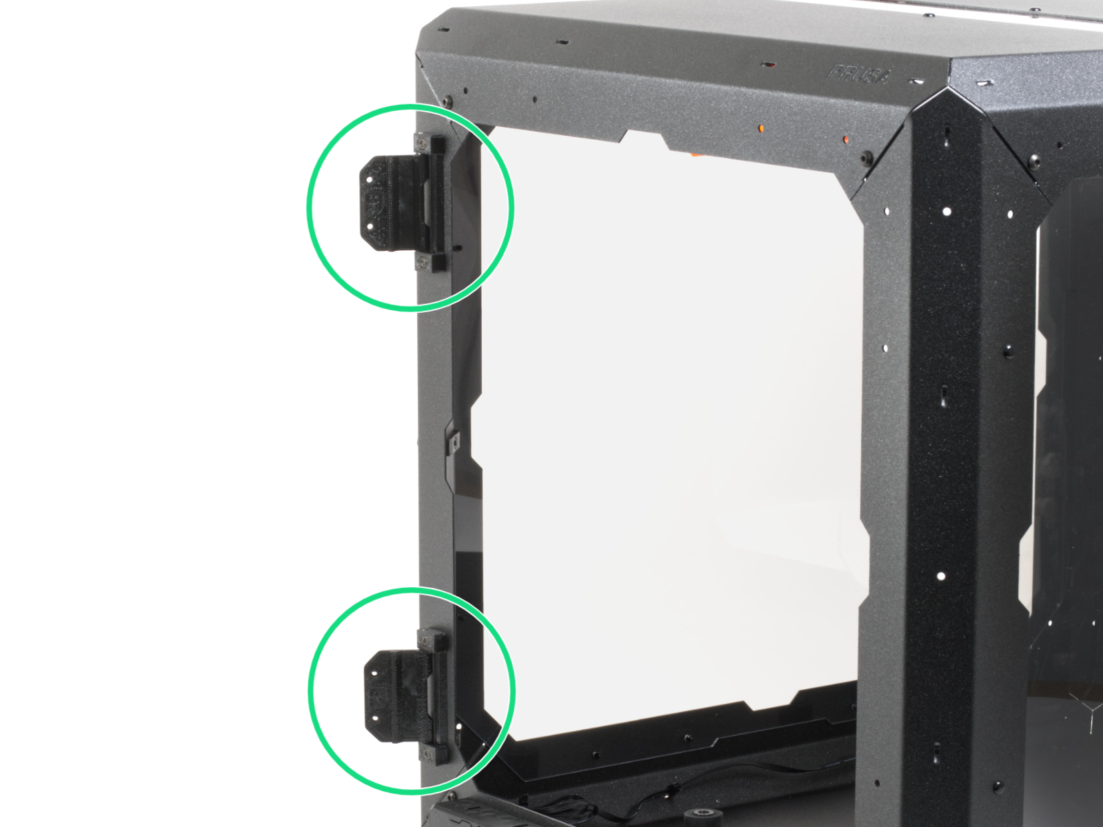
⬢Use the same procedure to mount the upper door-hinge.
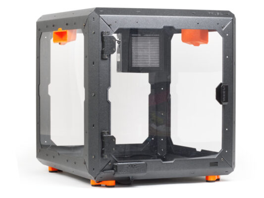
⬢Perfect! You just successfully assembled the Original Prusa Enclosure.
⬢Now it's time to put the printer inside. Let's move to chapter 3. Installing the printer.
Ce guide vous a-t-il été utile ?
Commentaires
Vous avez encore des questions ?
Si vous avez une question sur un sujet qui n'est pas traité ici, consultez nos ressources supplémentaires. Et si cela ne suffit pas, vous pouvez envoyer une demande à [email protected] ou via le bouton ci-dessous.