
⬢Para los siguientes pasos, por favor prepara:
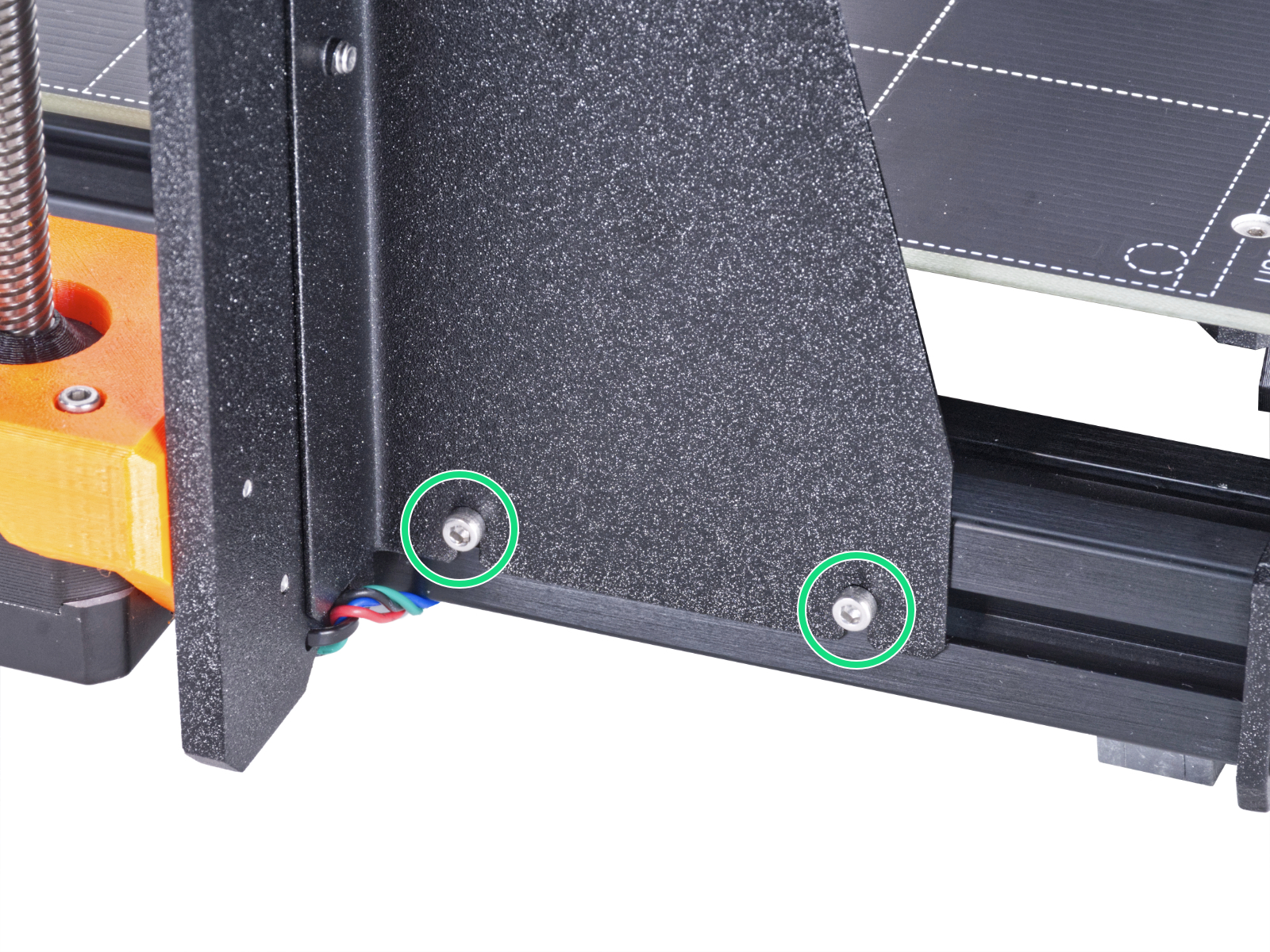
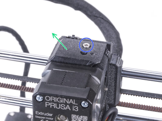
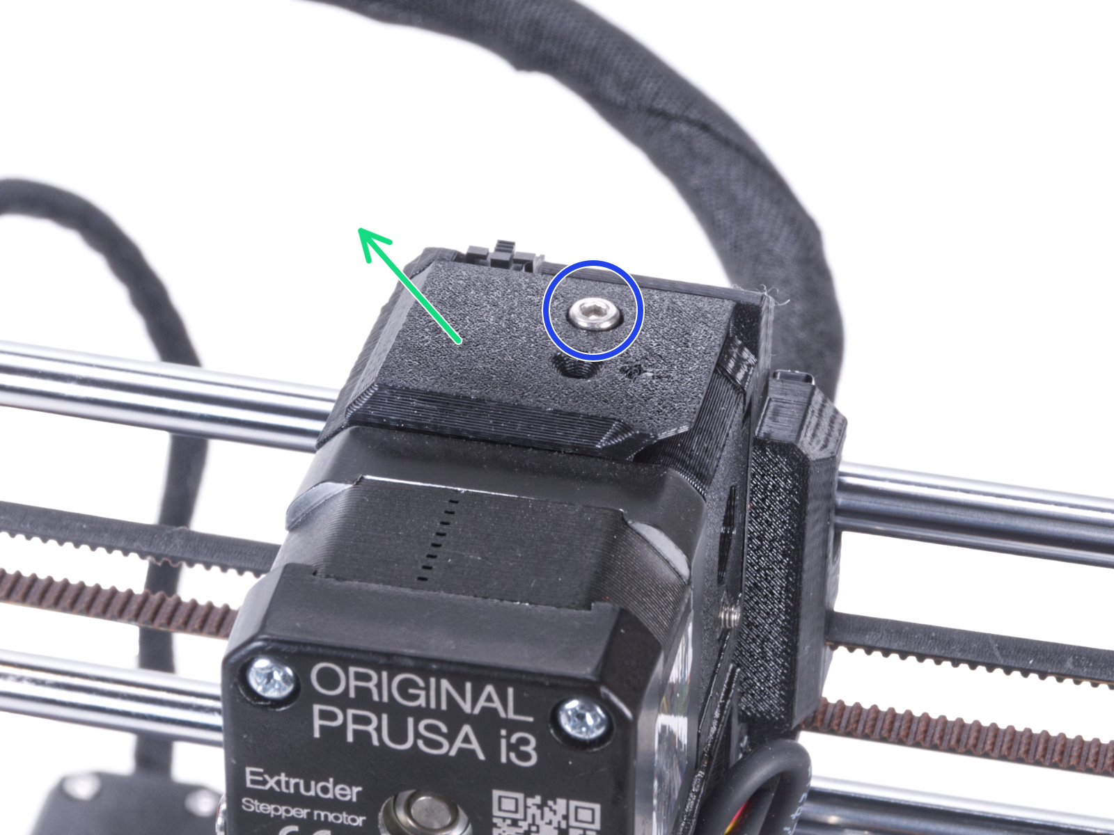
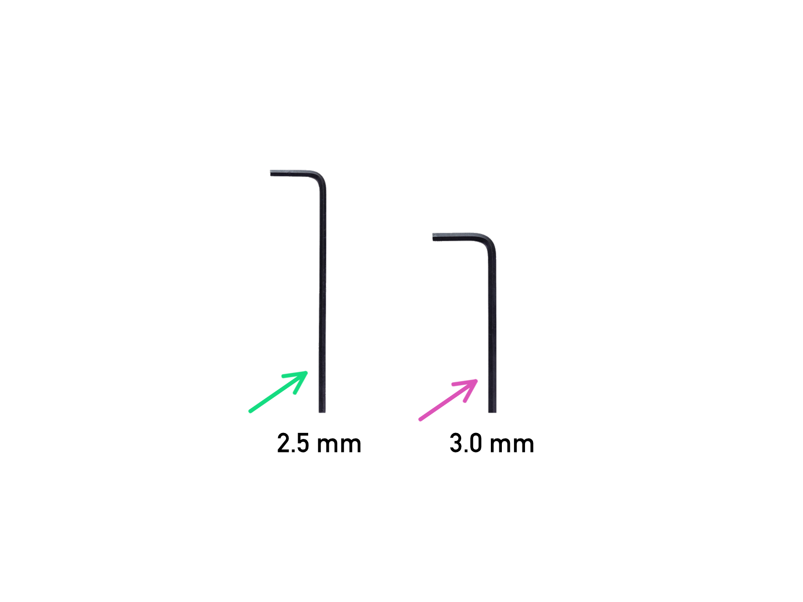
⬢2.5mm Allen key
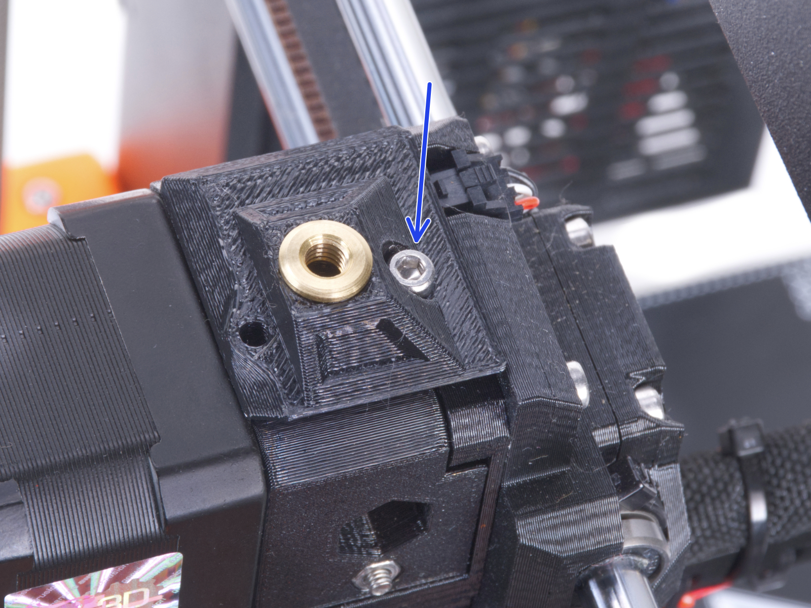
⬢3.0mm Allen key
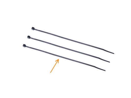
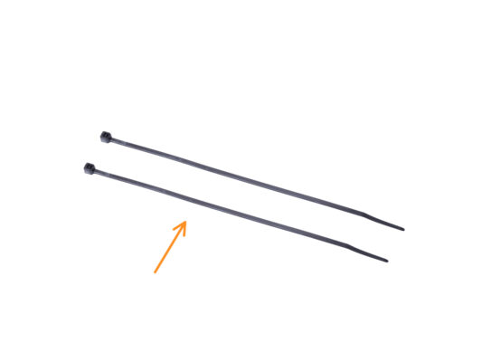
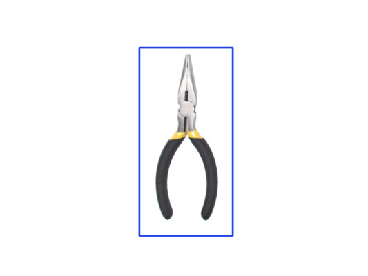
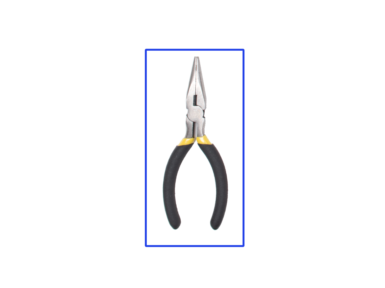
⬢Needle-nose pliers for cutting zip ties
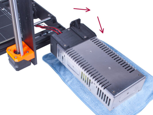
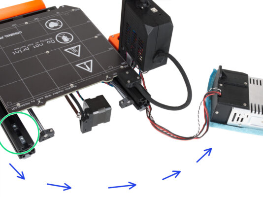
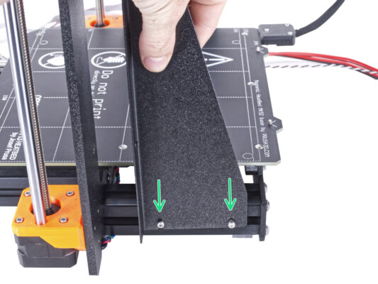
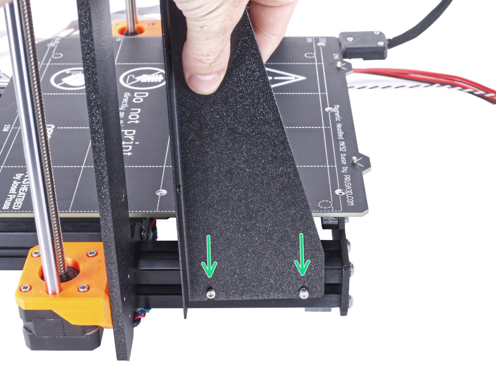
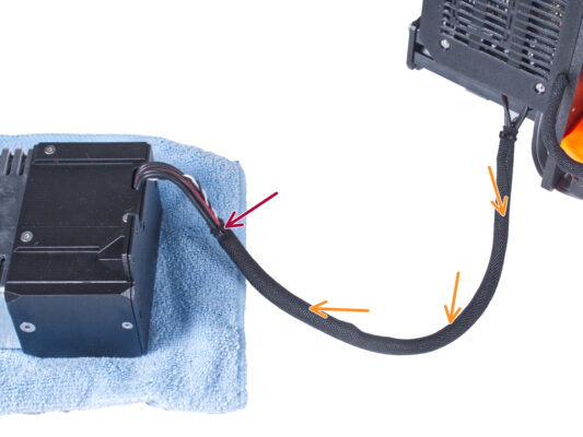
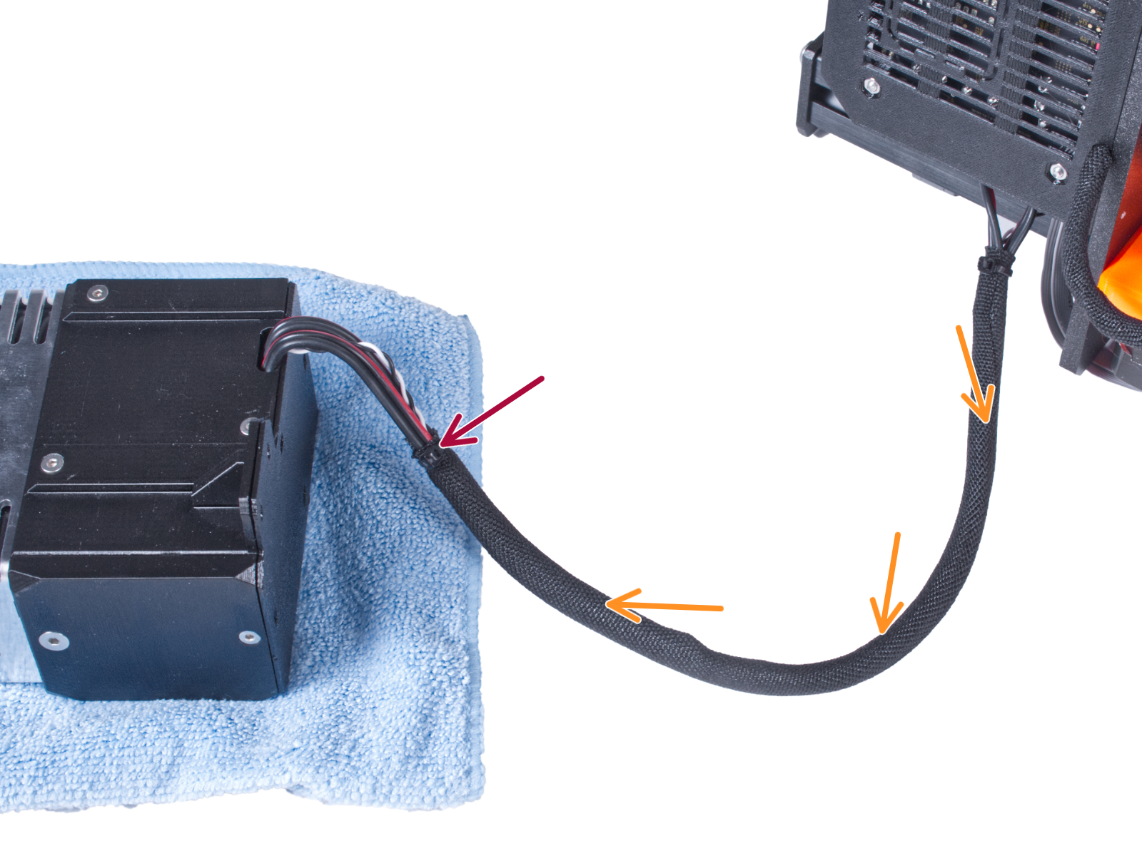
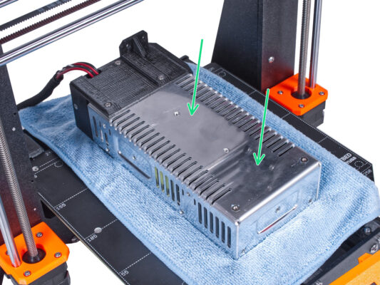
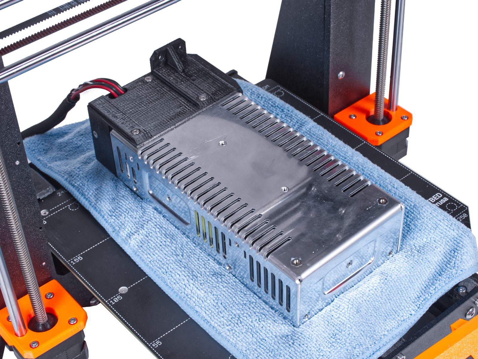
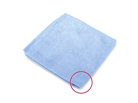
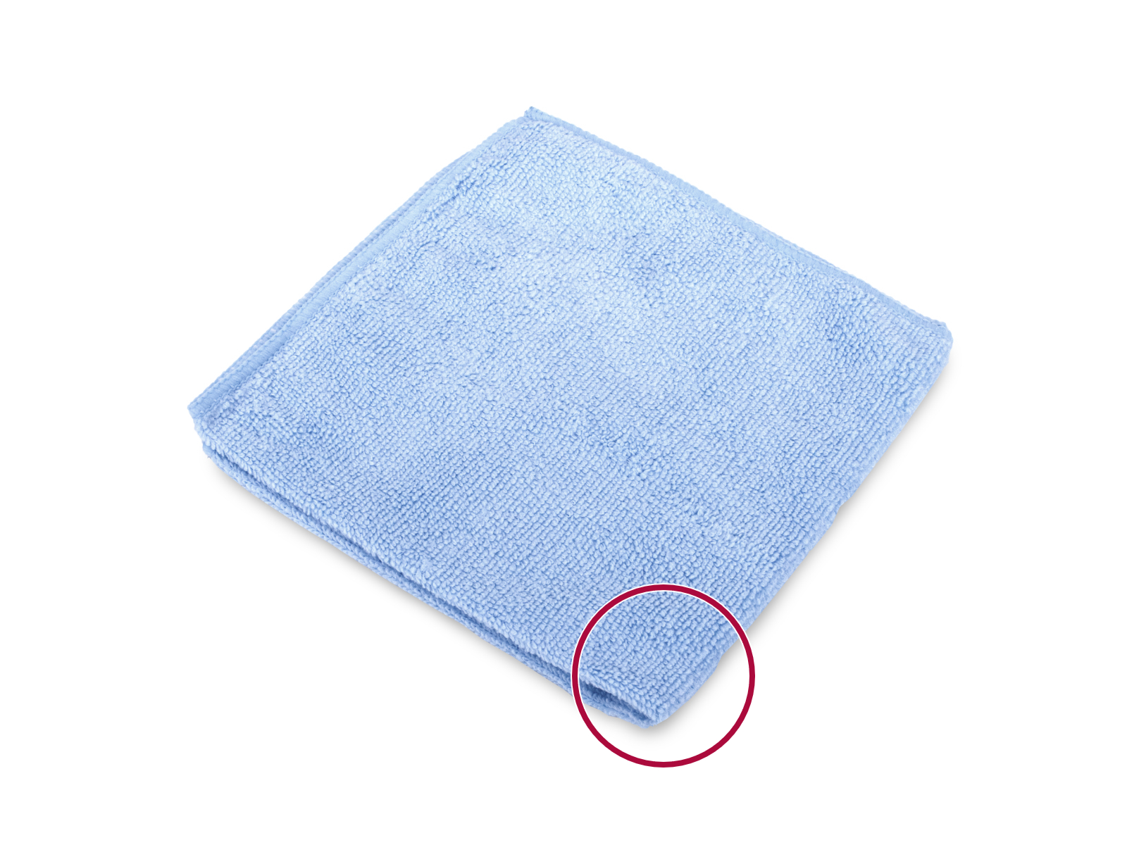
⬢Un trozo de tela o tejido (al menos 15x15 cm) para cubrir la base calefactable
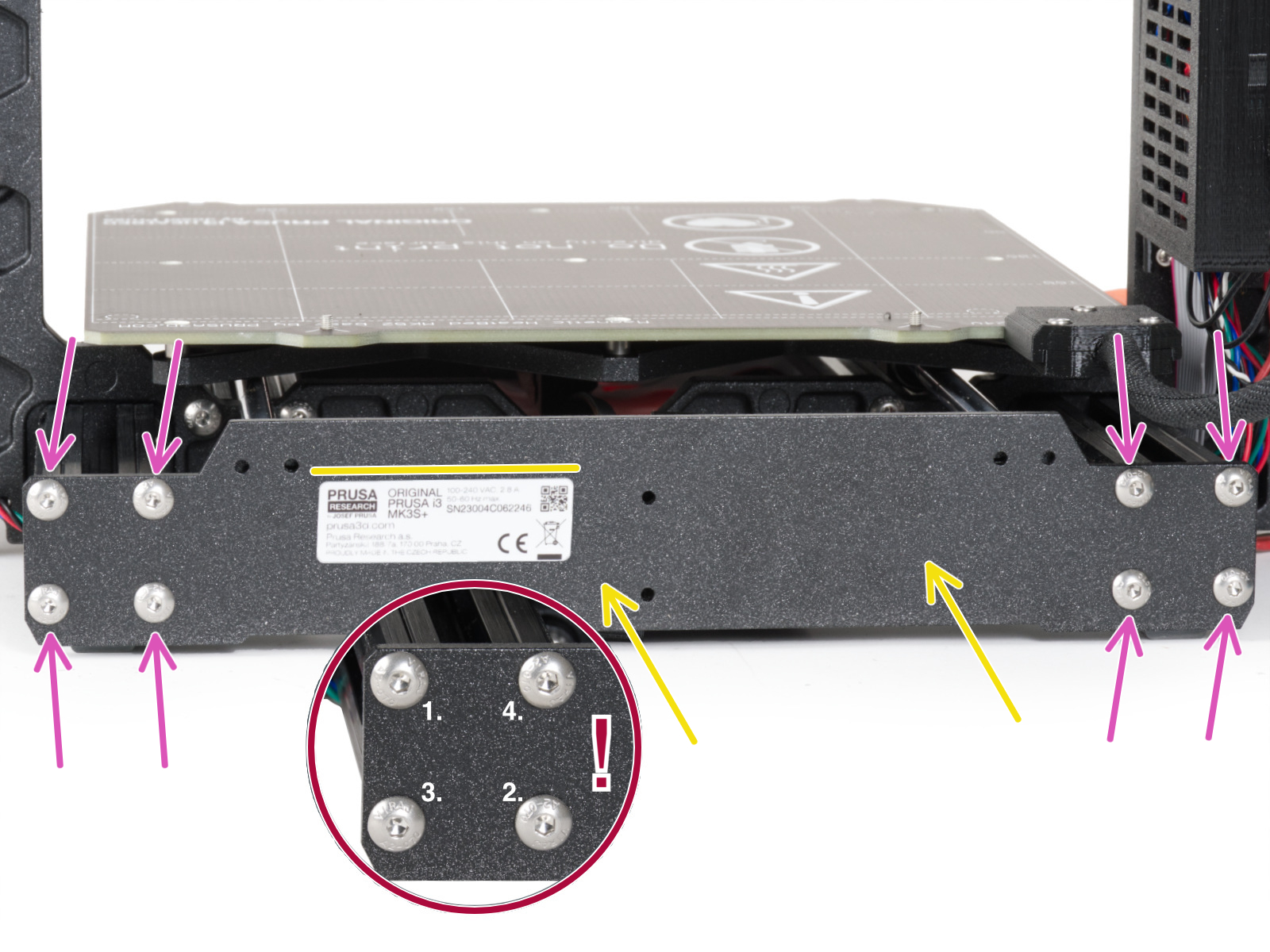
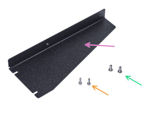
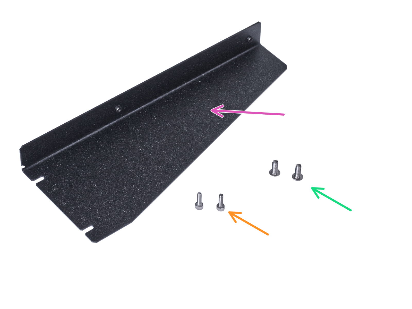
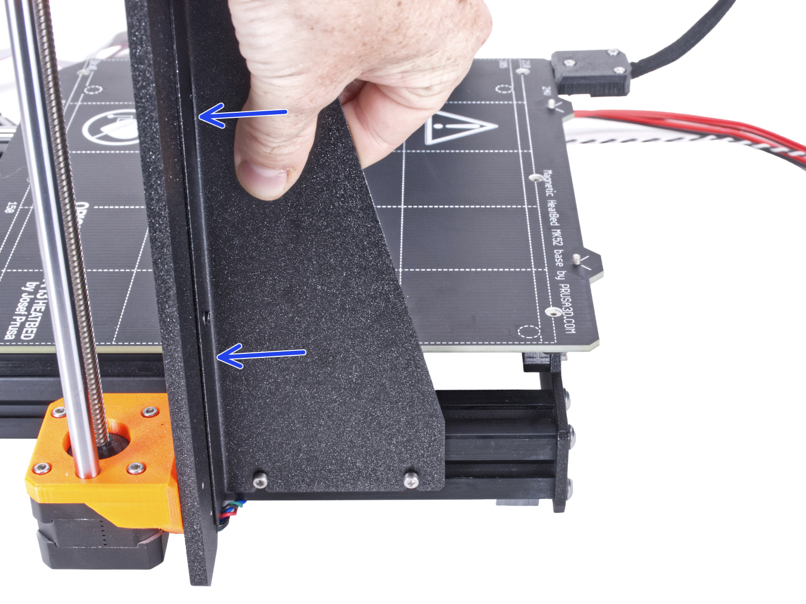
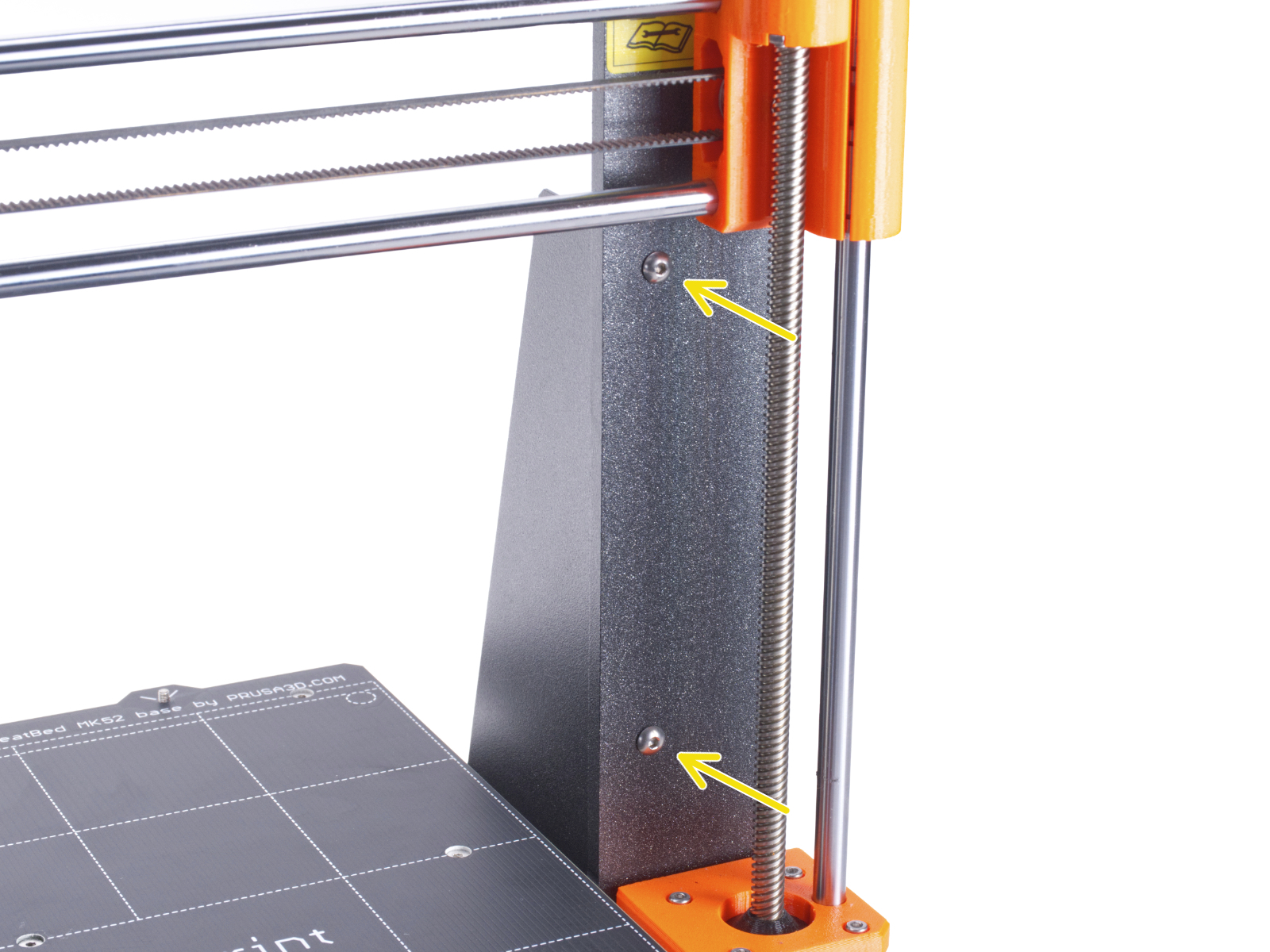
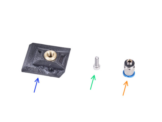
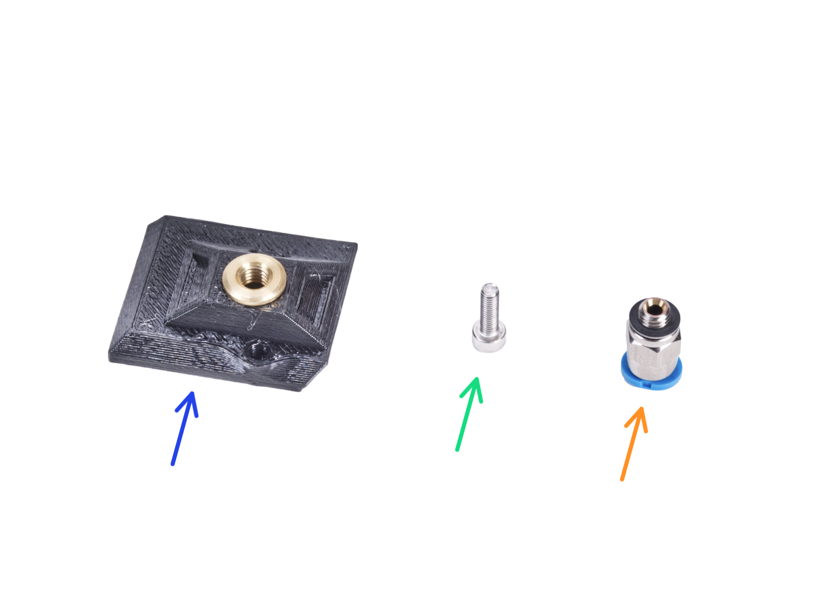
No deseches las piezas ni los elementos de fijación. Los reutilizaremos de nuevo más adelante.