Unlike FDM supports, which are usually lattice or grid-like, SLA supports are scaffolding tree-like structures with very thin tips. They’re easy to remove and they leave little to no traces on the printed object’s surface when removed. This also means that an insufficient number of supports can lead to unwanted effects – e.g. heavy objects can detach during the print. Supports go hand in hand with object orientation – by rotating the object to an optimal position, you can minimize the need for supports.

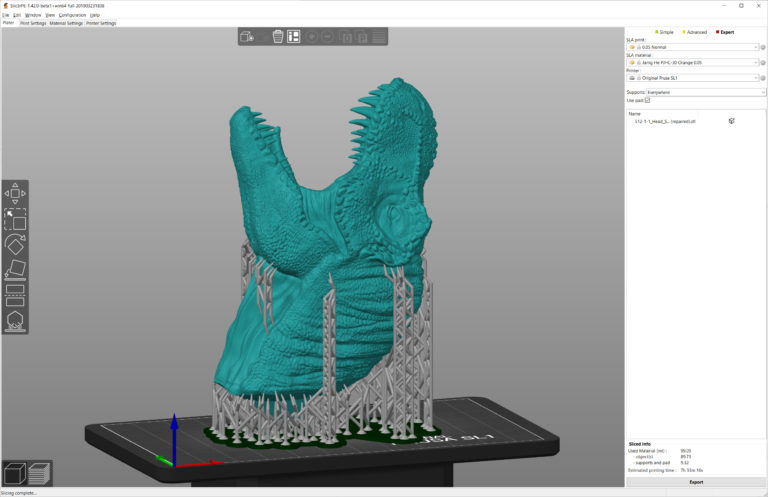
You can get rid of tons of supports if you rotate the object to an optimal position. Teeth on this T-rex head can be printed without supports
Also, keep in mind that removing the supports can leave tiny marks on the surface, so if your object has certain areas that should be completely flawless (an ornament on a piece of jewelry, face of an action figure), try to keep the supports away from them.
PrusaSlicer 2.0 is fully equipped for automatic tree support generation. How does it work?
- Select the object that requires supports
- Click the SLA support points icon
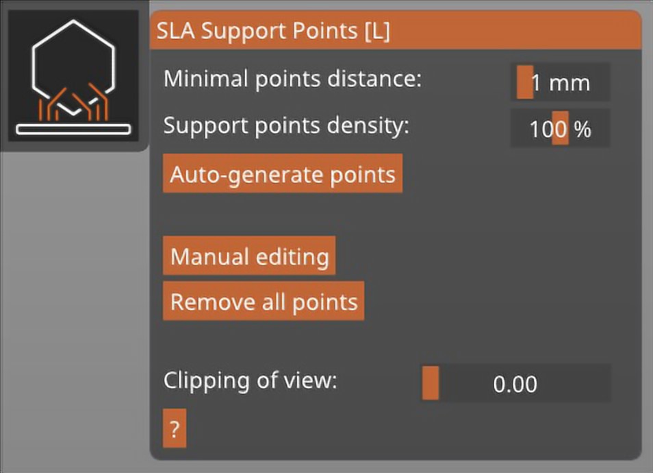
- Choose the support point density and minimal points distance (default values should work fine for a majority of objects)
- Click Auto-generate points and wait until the process is finished
- Use the Preview mode to inspect whether all “islands” are supported – if not, you can manually adjust the supports.

SLA Support menu in PrusaSlicer
Another thing that you should consider using is the pad. The pad (enabled by default) is a large structure at the base of the print, which serves as the foundation for the supports. While it’s possible to have supports printed directly on the aluminum printing platform, the pad will ensure much better stability.
Manual support editing
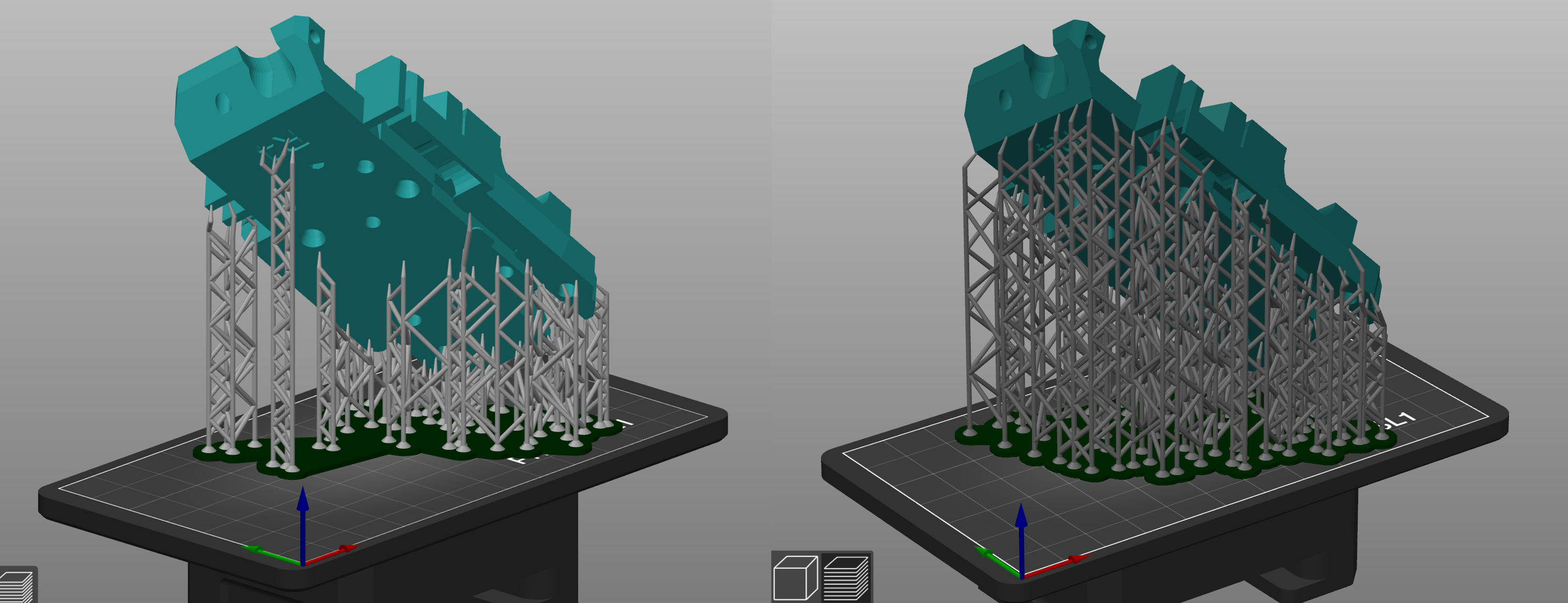
In some cases, the automatic support generation doesn’t deliver a 100% perfect result – this is normal since imported objects can be infinitely complex. We’re constantly improving our support generation subroutines to prevent these situations from happening. Either way, on certain occasions, supports have to be added manually – this can be done even when there are already auto-generated supports in place.

Comparison of automatically generated supports and manually edited supports
Click the Manual Editing button. Previously generated supports will temporarily disappear to give you a better overview of the model. Use the left mouse button to add new support points. You can tweak the support thickness in manual editing mode by using the Head diameter slider, or you can go to Print settings – Supports and modify the following parameters to increase the thickness of supports:
- Support head front diameter: 0.6 mm
- Support head penetration: 0.6 mm
- Support pillar diameter: 1.3 mm
Useful shortcuts
Shift + Left mouse drag Add multiple points to the selection
CTRL + Left mouse click Add single support point to the selection
ALT + Left mouse click Remove single support point from the selection
ALT + Left mouse drag Remove multiple points from the selection
CTRL + A Select all points
CTRL + Mouse Wheel Move the clipping plane