ES
  • English
  • Čeština
  • Italiano
  • Deutsch
  • Polski
  • Français
Iniciar sesión

10B. Configuración y Calibración MK3S+
Menu

10B. Configuración y Calibración MK3S+

10B. Configuración y Calibración MK3S+
Relevante para :
Ultima actualización 4 months ago
10B. Configuración y Calibración MK3S+
 Dificultad
Muy difícil
 Pasos
31
 Idiomas disponibles
ENCSPLDEITFR
Herramientas necesarias para este capitulo
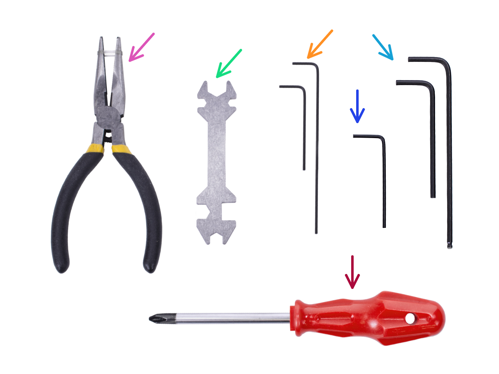
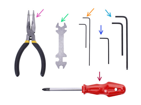
Por favor prepara las herramientas para este capítulo:
Unikey for tightening up the Festo fittings.
1.5mm Allen key for Filament sensor calibration
Llave Allen de 2.5mm para tornillos M3
Phillips screwdriver for power cable terminals
Attaching the MMU unit (part 1)
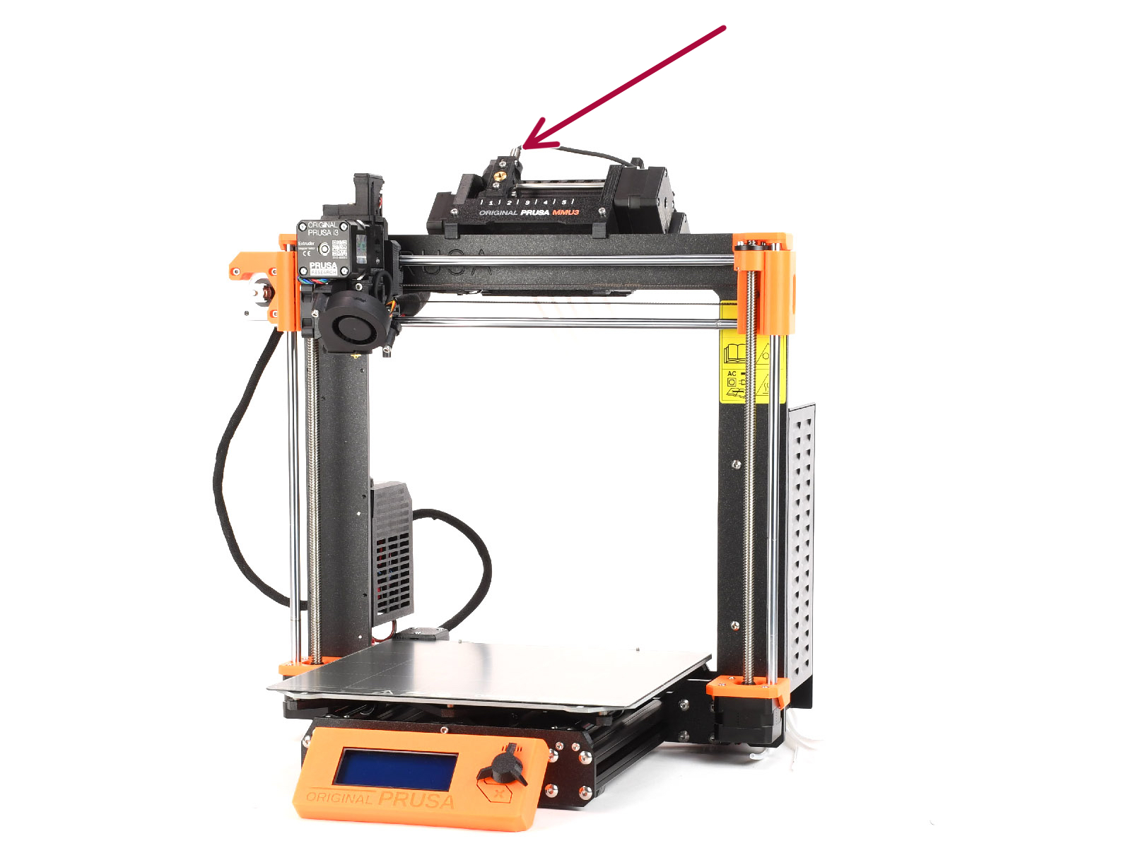
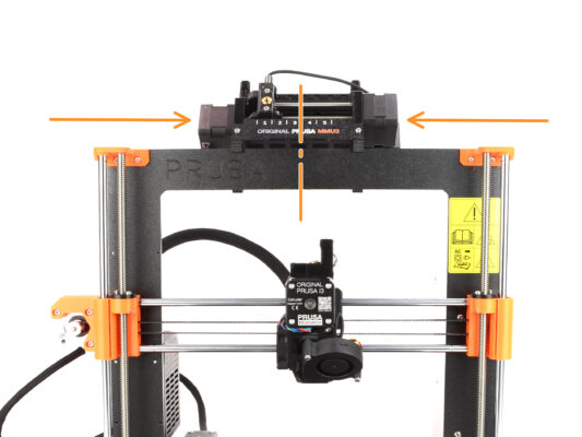
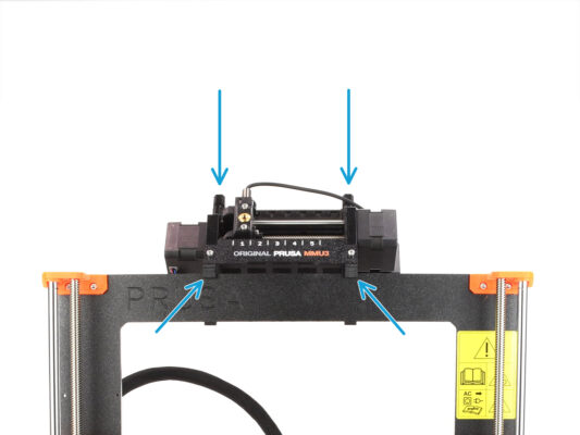
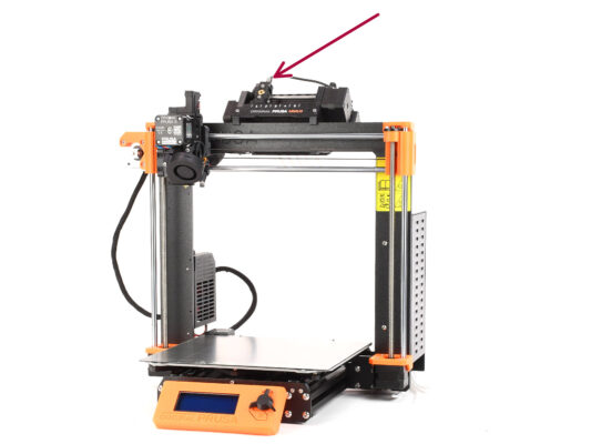
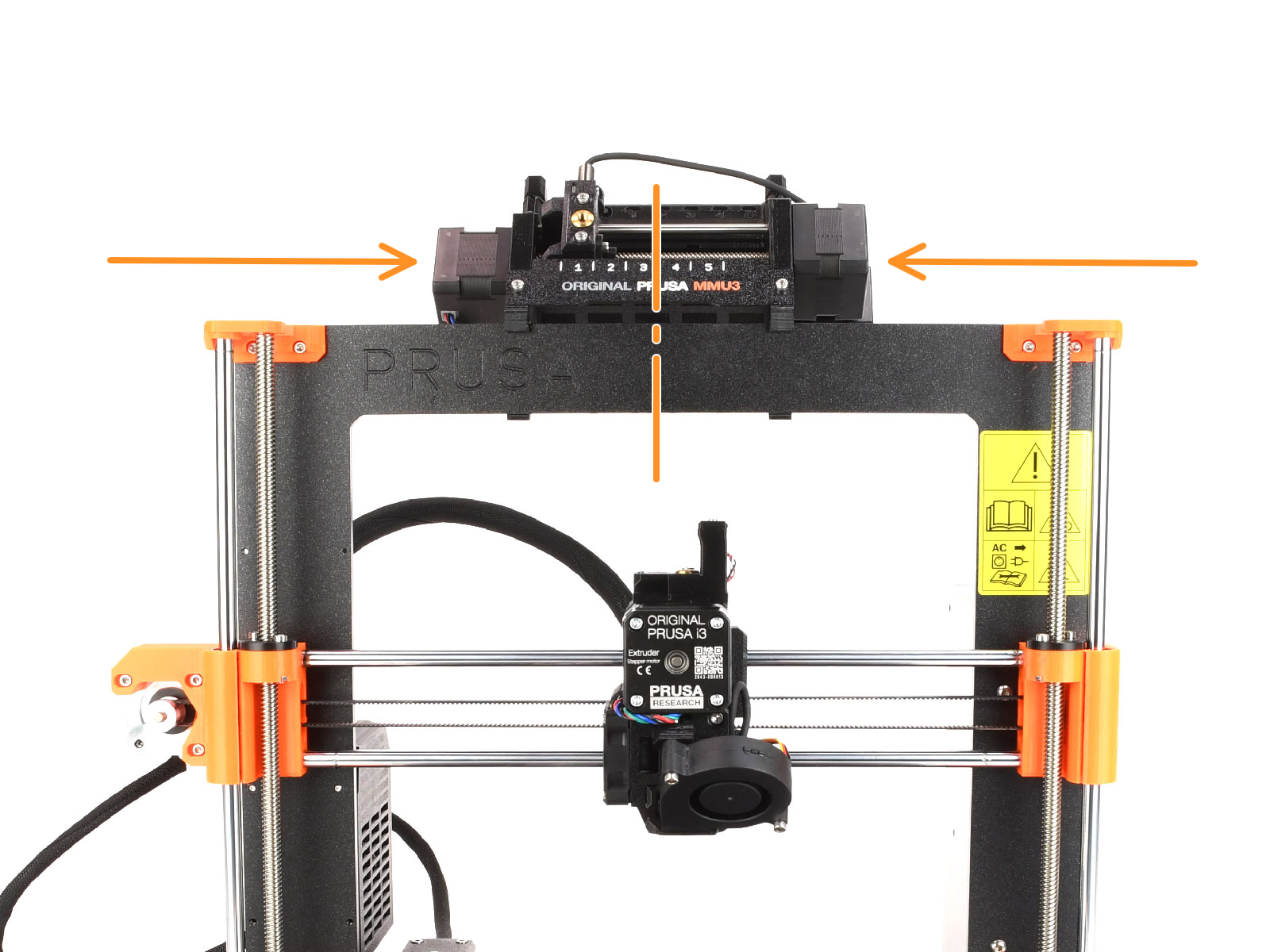
The MMU3 unit should be placed in the middle of the top part of the printer's aluminum frame.
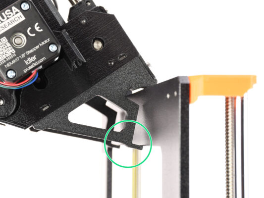
Place the MMU3 unit onto the frame.

Attach it just by the top hooks.
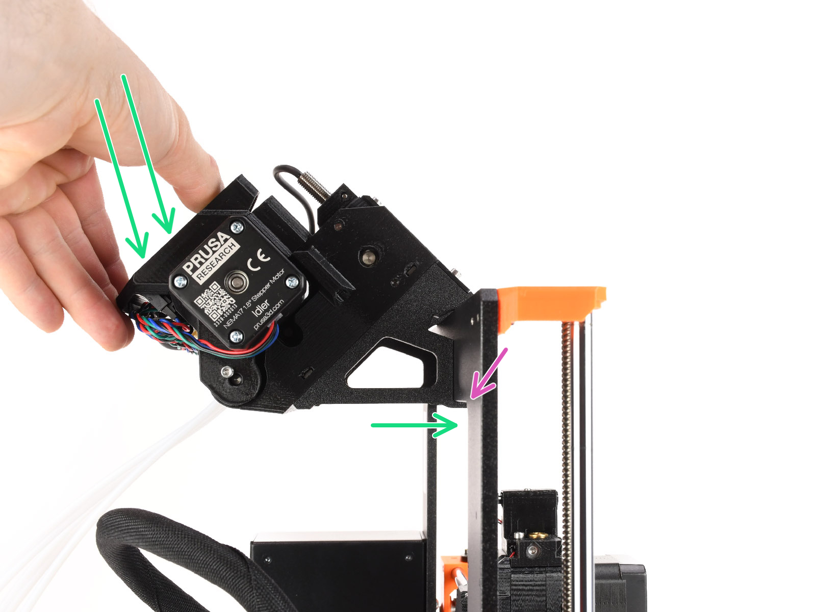
Look from behind, there are "clamps", which will be used to lock the unit to the frame in the next step.
Attaching the MMU unit (part 2)
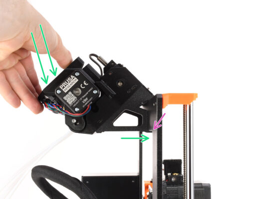
Make sure the unit is in the middle of the frame. Once we engage the clamps, it won't move left and right as easily anymore.
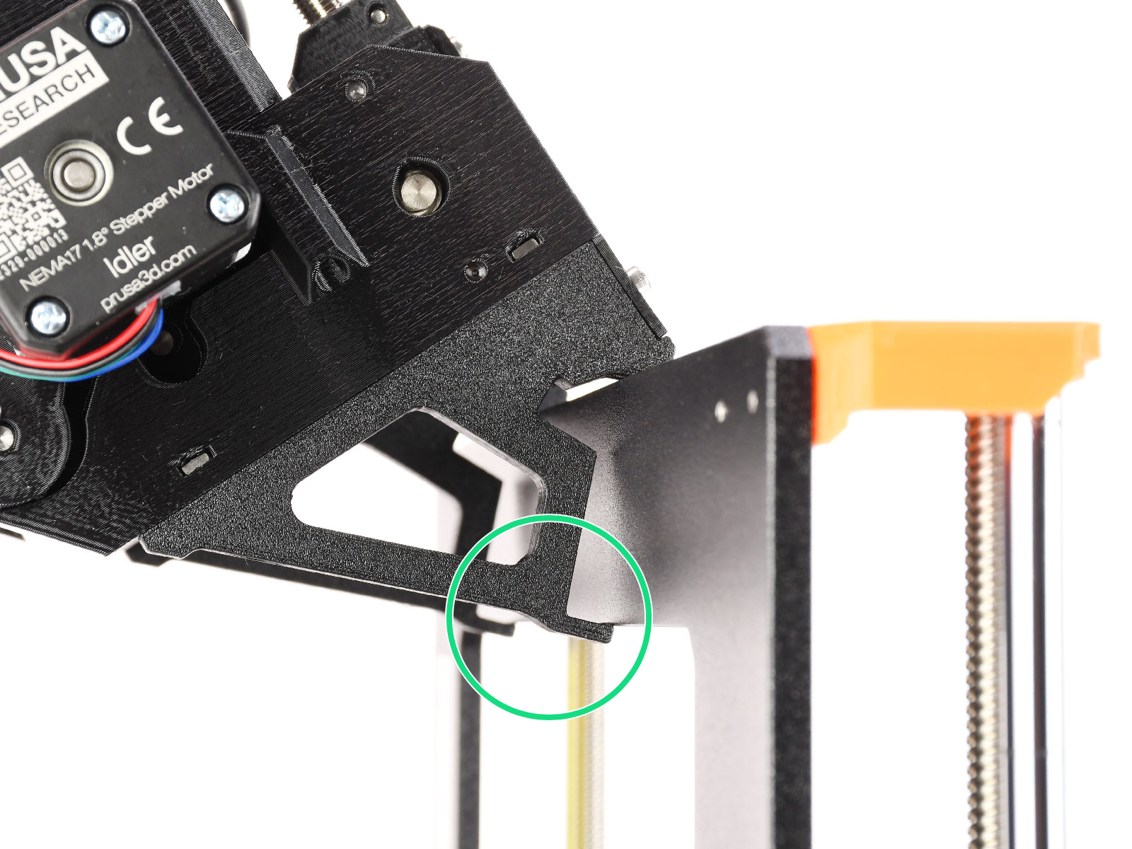
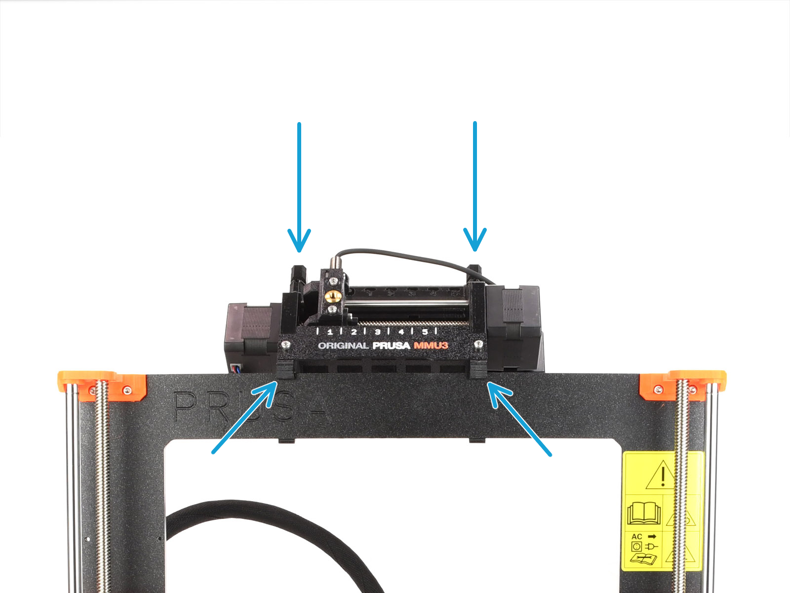
Press the back part of the MMU3 unit downwards slightly, until the clamps lock to the frame.
Check that both bottom clamps on the unit are fully engaged.
If you need to remove the unit from the frame, simply lift the back part up to disengage the clamps.
Attaching the cable bundle
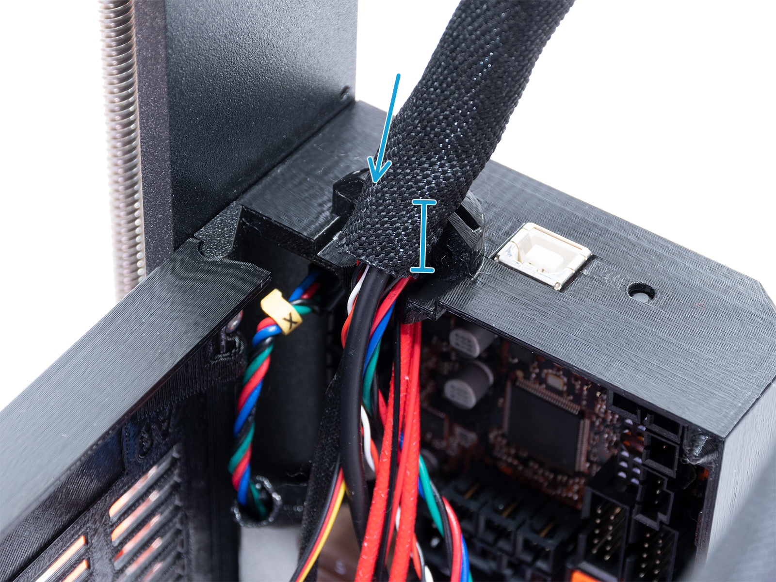
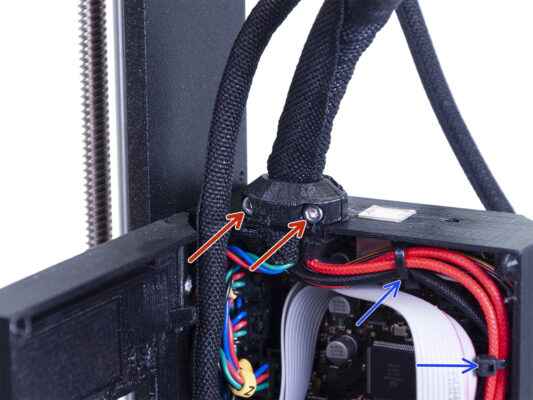
Let’s move onto the electronics box side of the extruder cable bundle.
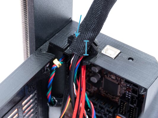
Tighten up the sleeve around the cable bundle. Hold it tight before you fix it in place with the clip and the screws. The textile sleeve should be held by the cable clip
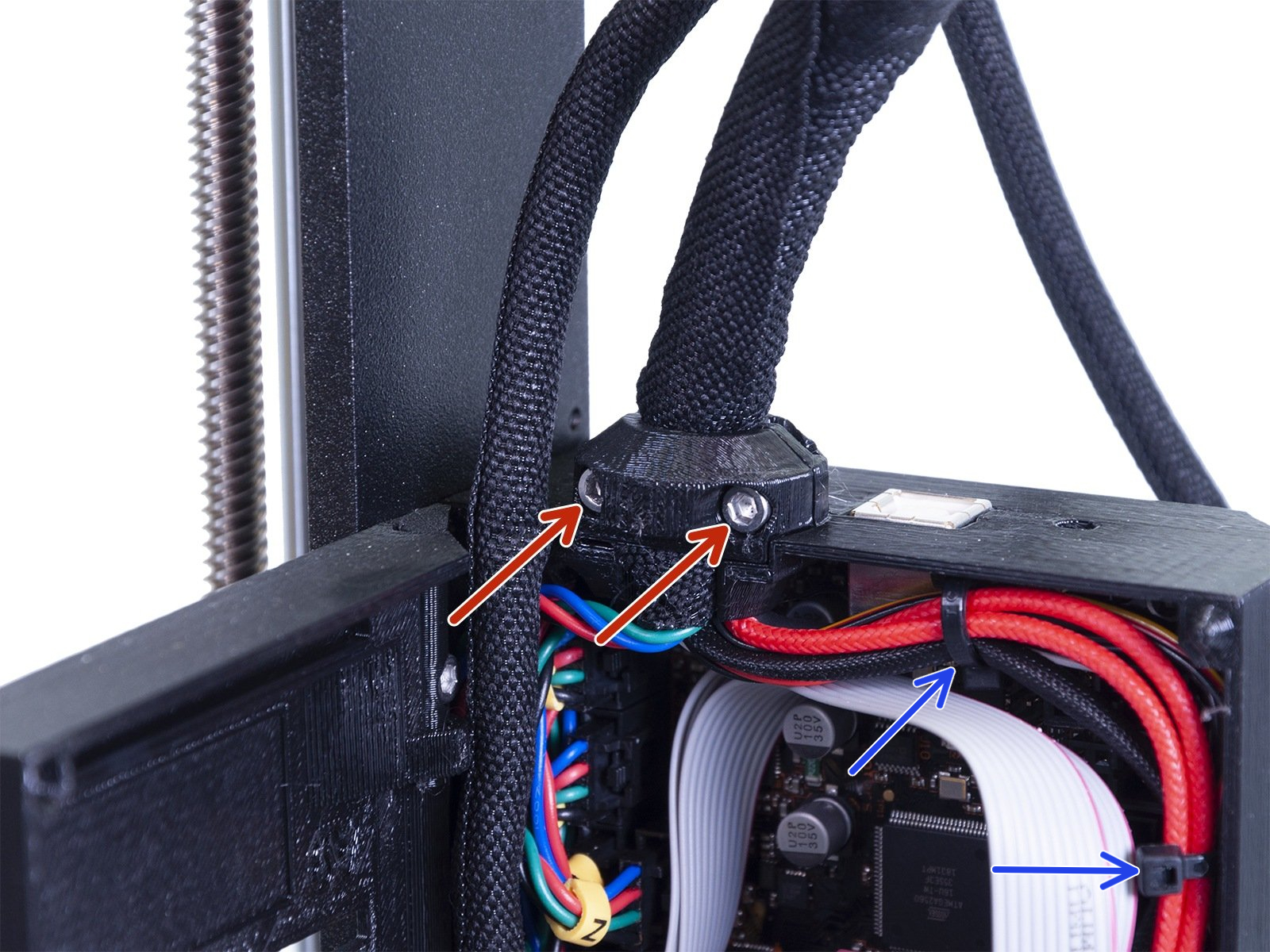
Fix the cable bundle in place by tightening the two M3x10 screws holding the Extruder-cable-clip. Make sure no cable is getting pinched!
For easier cable-management inside the electronics box, attach the extruder cable bundle to the hooks on the inside of the Einsy-base with two zip-ties in the marked positions.
Guiding the MMU cable
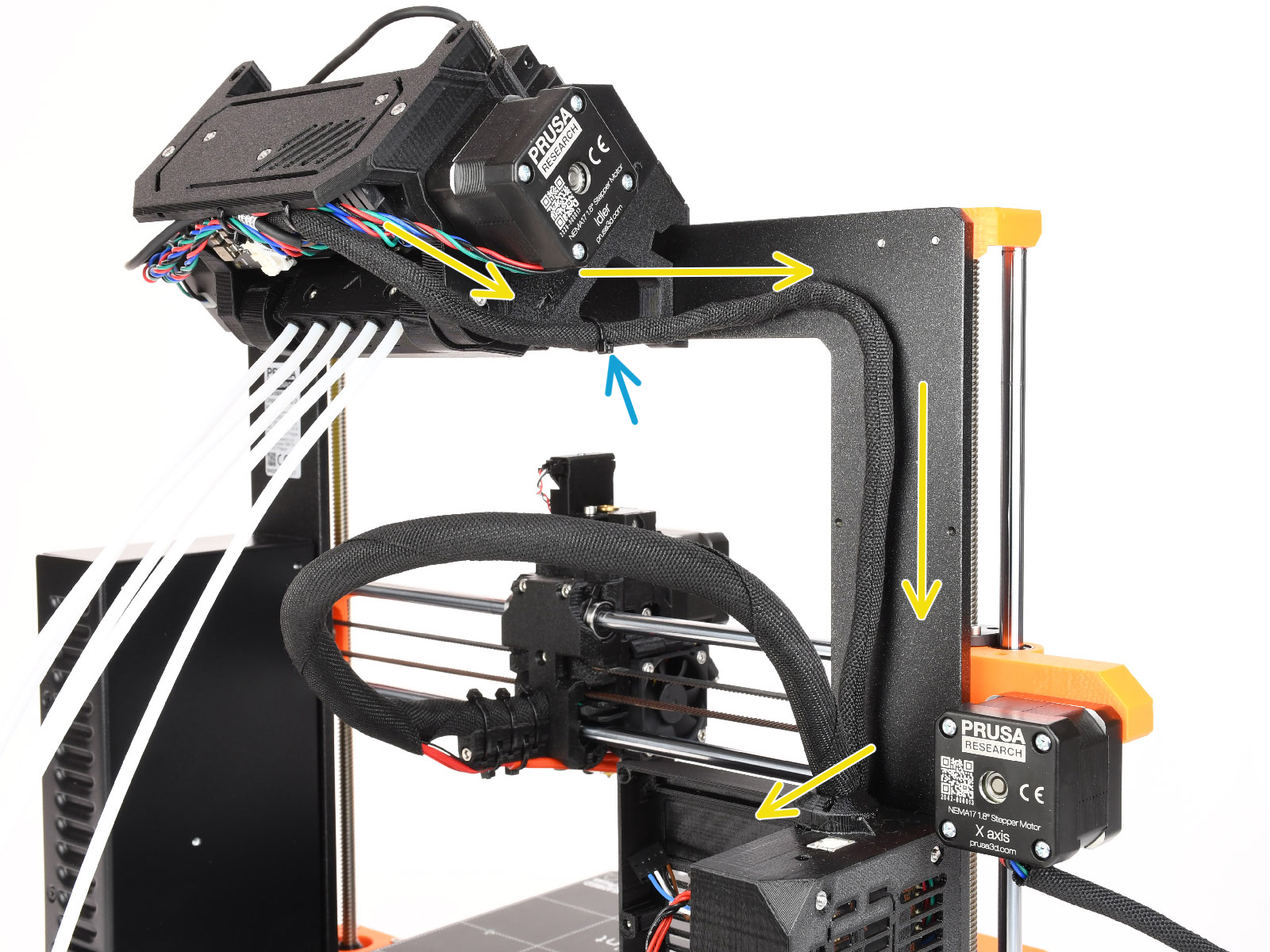
Now, we will guide the cables from the MMU unit into the printer.
Make sure the printer is turned OFF and unplugged from the wall outlet. Do not ever connect or disconnect the MMU unit while the printer is ON.
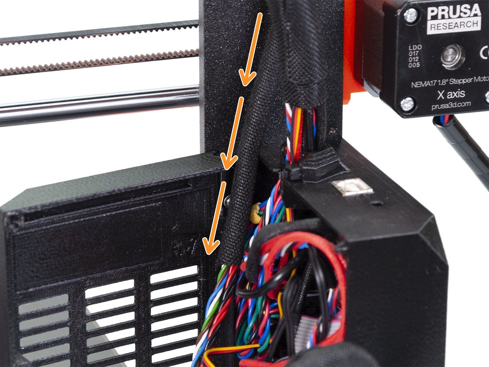
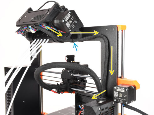
Introduce el haz de cables de la unidad MMU hacia la electrónica de la impresora. El cable debe colocarse justo al lado del bastidor de la impresora.
You can fix the cable to the MMU3 holder using a zip-tie in marked location. Make sure it points to the side - not down. Otherwise, it might interfere with the extruder cable while printing.
Guide the cable towards the electronics box.
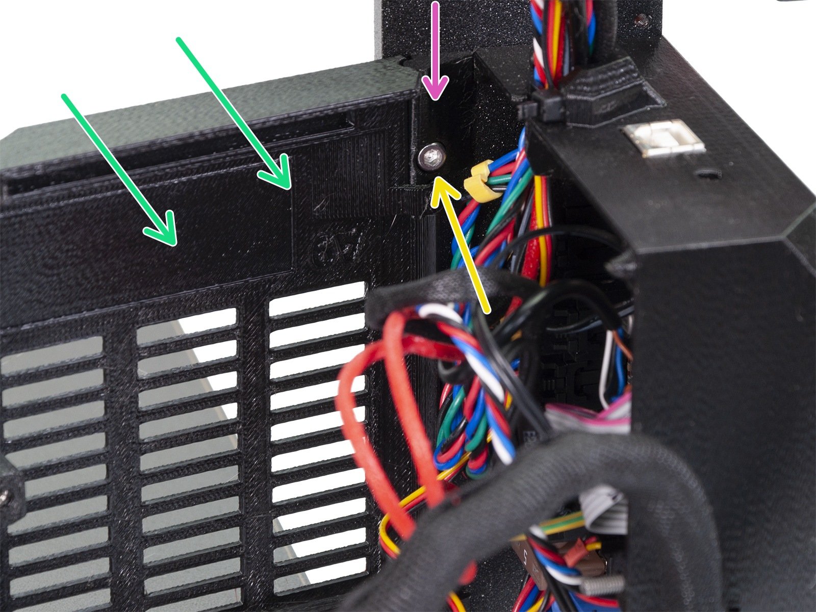
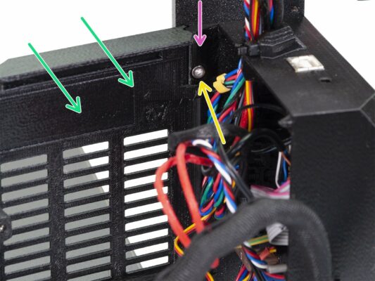
MK3S+ Trimming the electronics box door
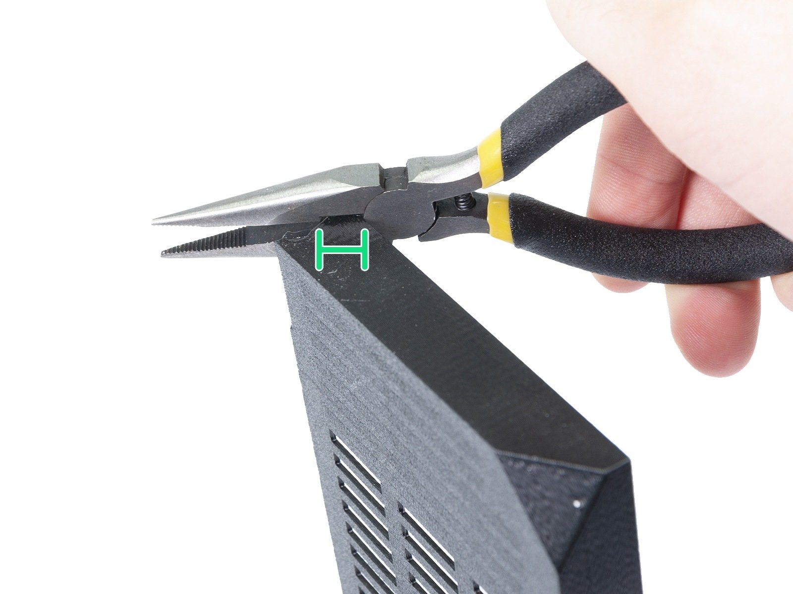
WARNING: We need to cut part of the plastic on the electronics box door to make some room for the MMU cable. Make sure you wear protective eyewear!
If you’re upgrading from the MMU2S to MMU3 and your door has been trimmed already in the past, you can skip this step.
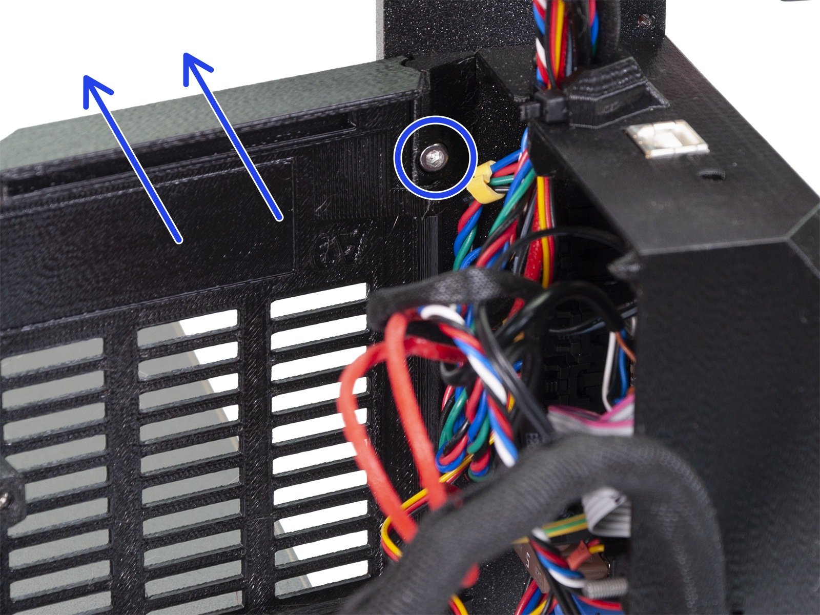
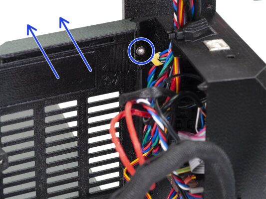
Release and remove the M3x10 screw in the upper hinge. Remove the door together with the hinge by pulling it up.
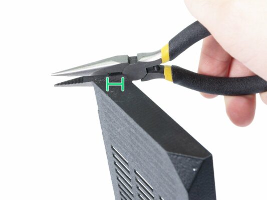
Using pliers, carefully cut the inner corner of the door. The MMU cable bundle will need some more clearance in the marked location.
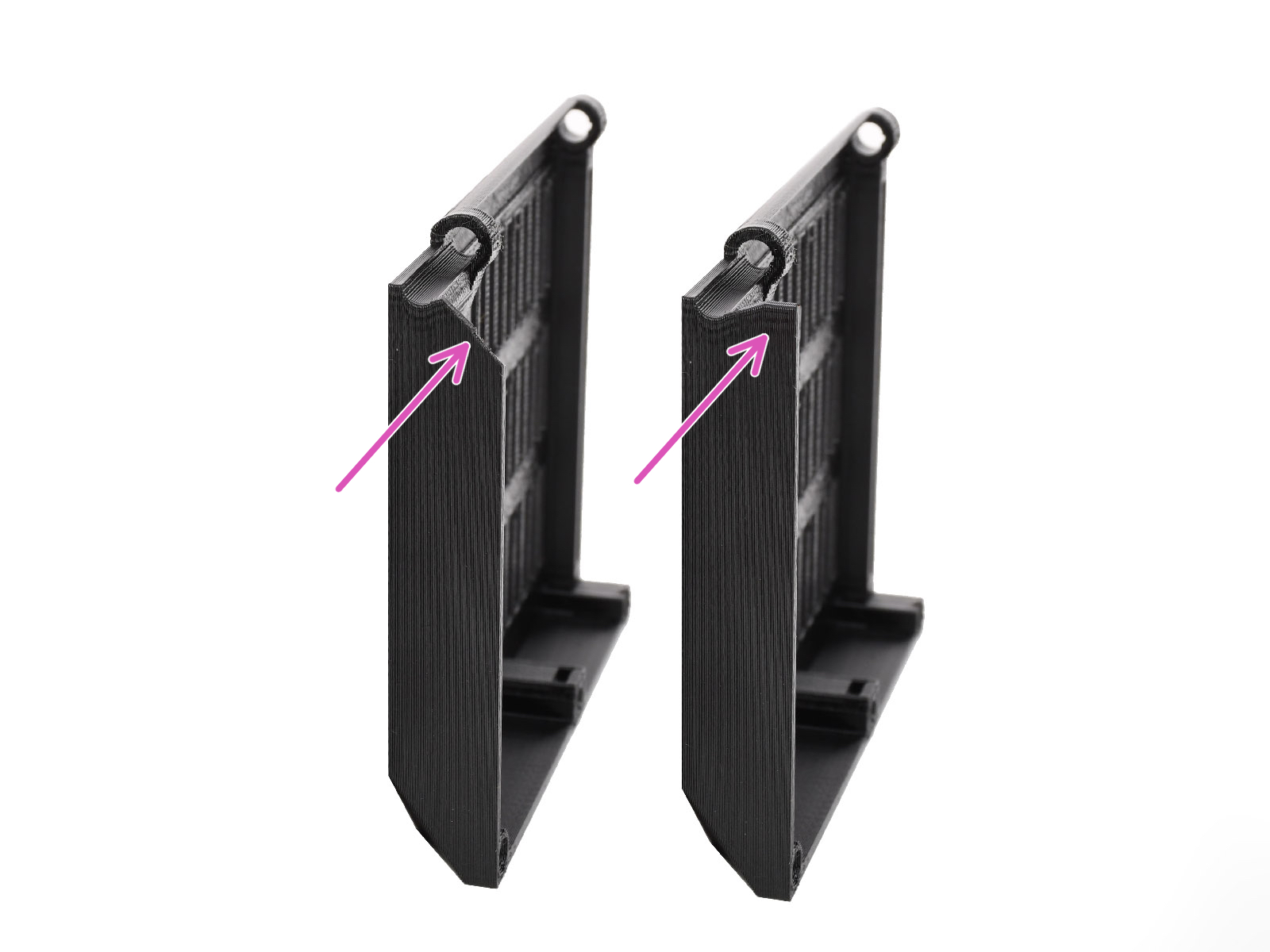
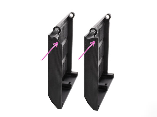
Comparison between the trimmed door (left) and its original shape (right).
MK3S+ Trimmed electronics door installation
Re-attach the door back onto the bottom hinge.
Make sure the top hinge is in place.
Attach the top hinge to the printers frame using the M3x10 screw.
Make sure there is enough clearance for the MMU3 cable when you close the door.
The cable should be held by the door but must not be squished too much. Otherwise, you risk damaging the cable!
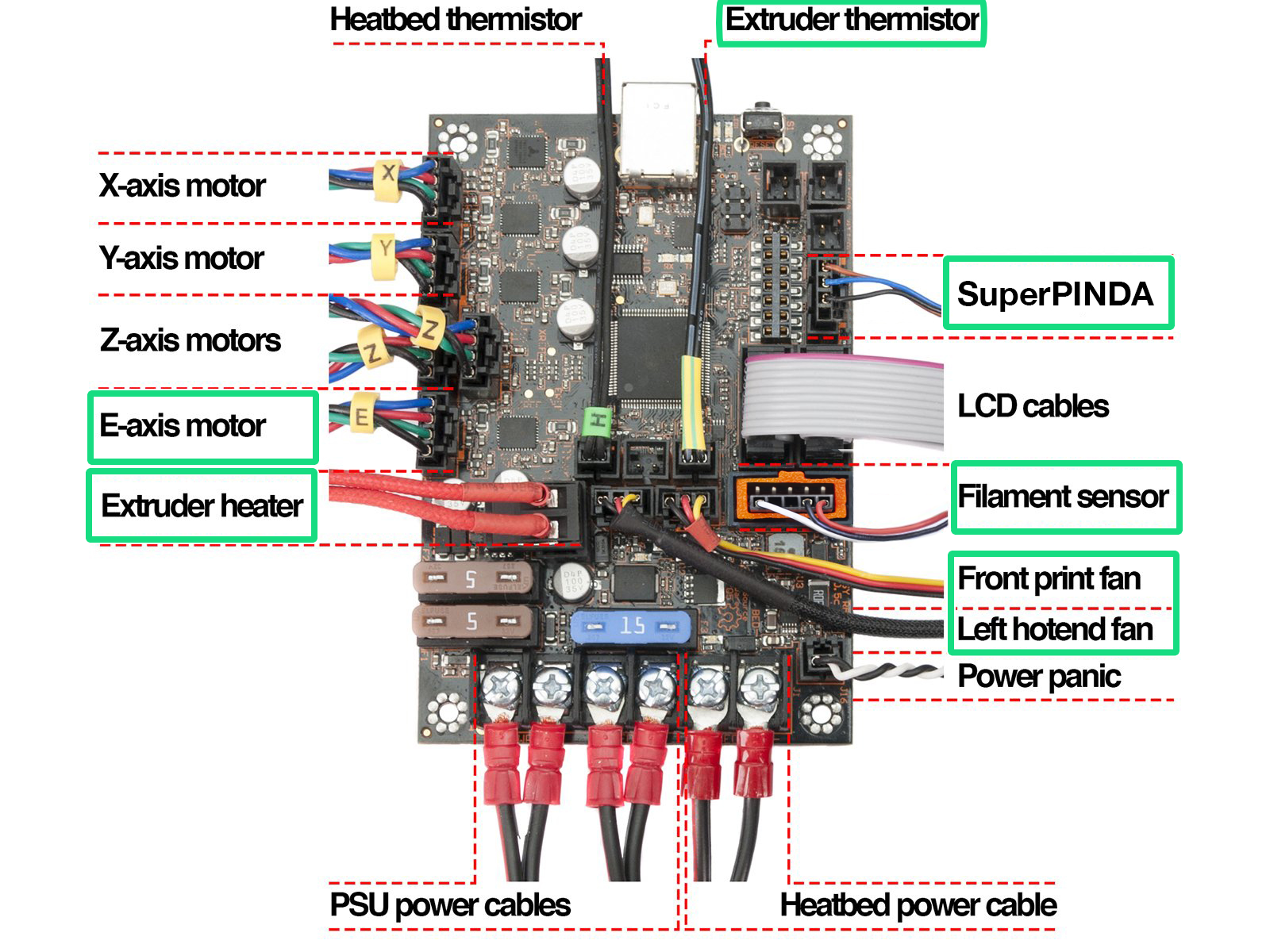
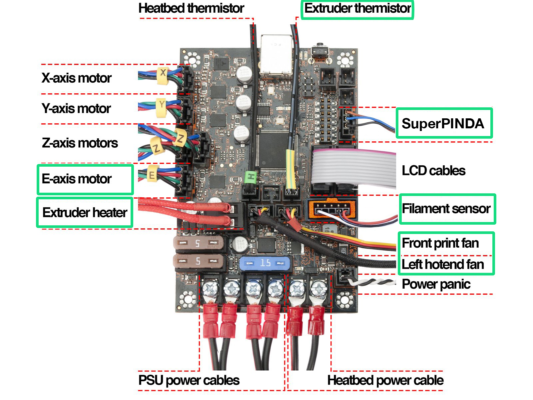
MK3S+ Electronics wiring diagram
In the following step, we will connect the cables to the already existing connections on your Original Prusa MK3S+. Please, proceed very carefully.
Follow the diagram shown here in case you need to reconnect any of the extruder cables into the Einsy Rambo control board.
Since, MK2.5S printer isn’t officially supported in combination with the MMU3, this guide doesn’t cover connecting the electronics on it. Instead, it is described in the MK2.5S MMU2S guide.
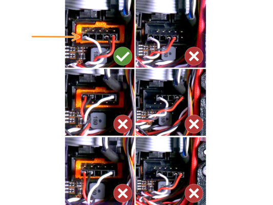
MK3S+ Connecting the data and FS cables
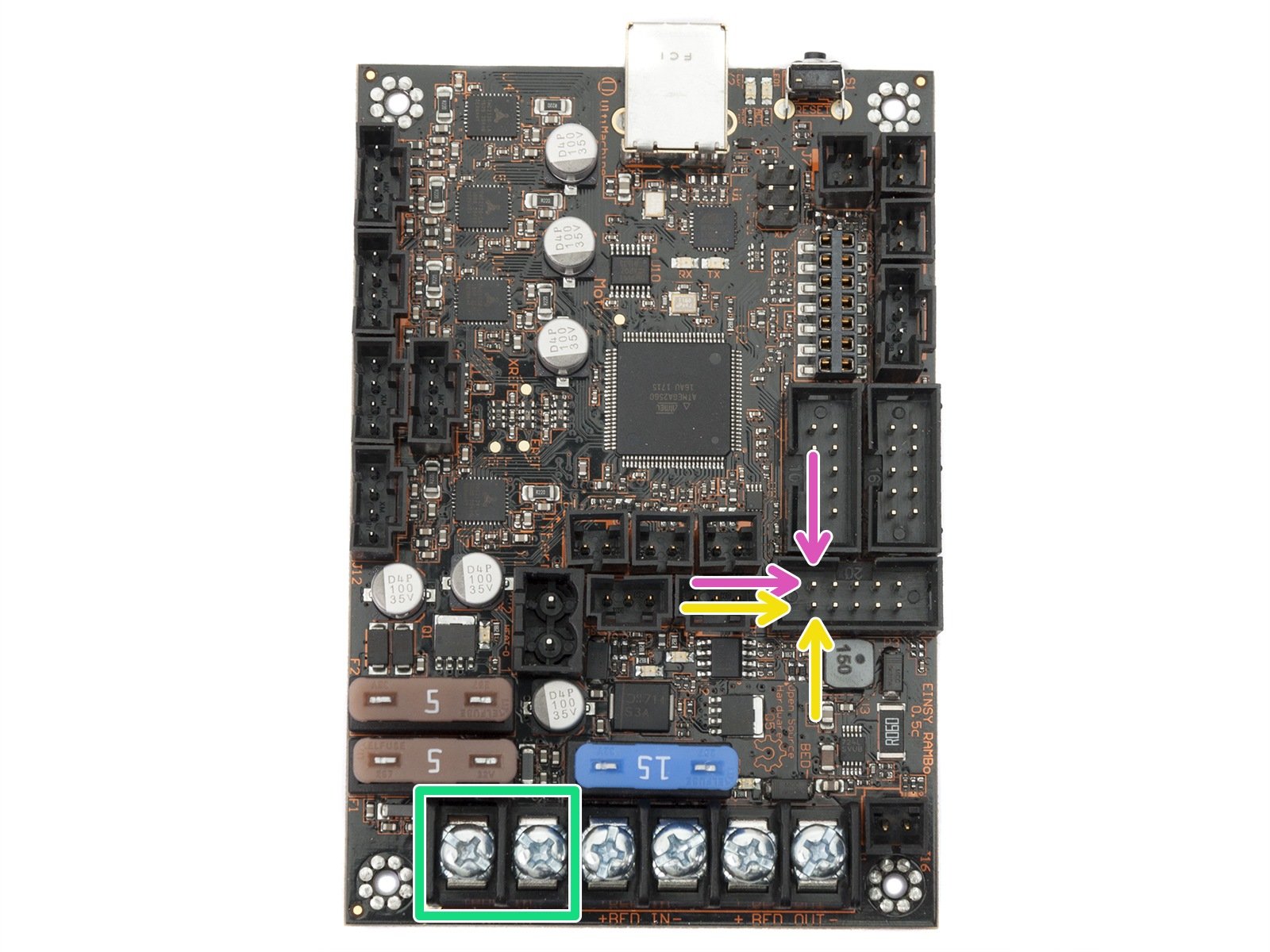
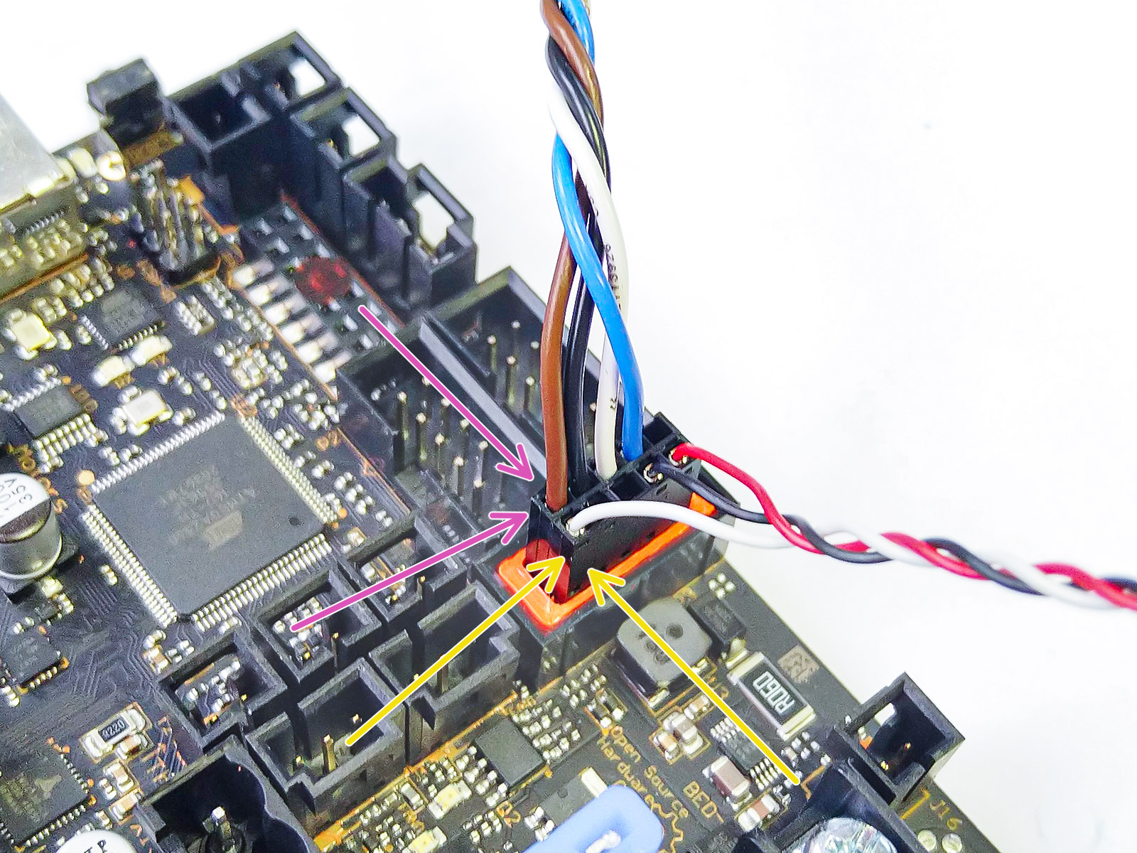
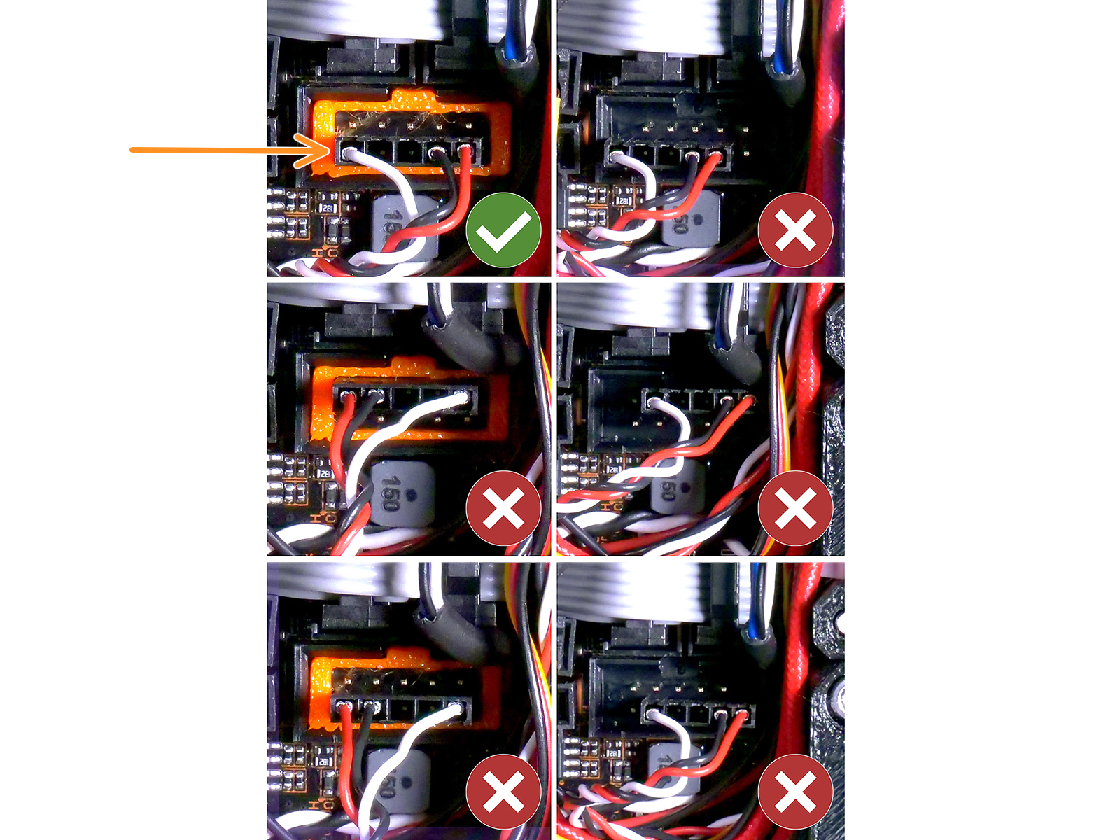
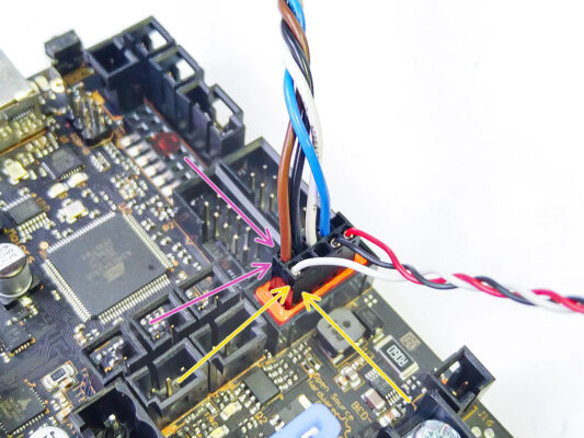
Observe la posición marcada. El conector del cable de señal del MMU debe ir aquí. (fila superior de los pines, cable marrón en el conector debe estar mirando hacia la izquierda)
Upper row of the pins, the brown wire in the plug must be facing left!
El cable del sensor de filamento IR está justo debajo del cable de señal de la MMU.
Bottom row of the pins, the white wire is facing left.
Verify the IR Filament sensor connector is installed correctly. Make sure it is plugged in correctly as there are several ways for it to go wrong!
¡Asegúrate de que el cable de señal está conectado adecuadamente a todos los pines!
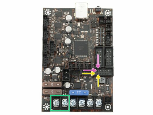
Conexión de los cables de alimentación MK3S+

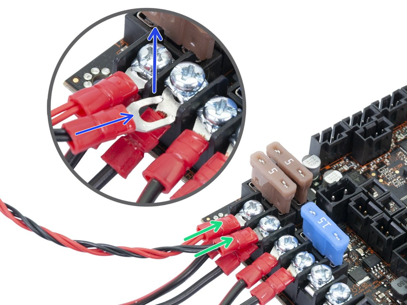
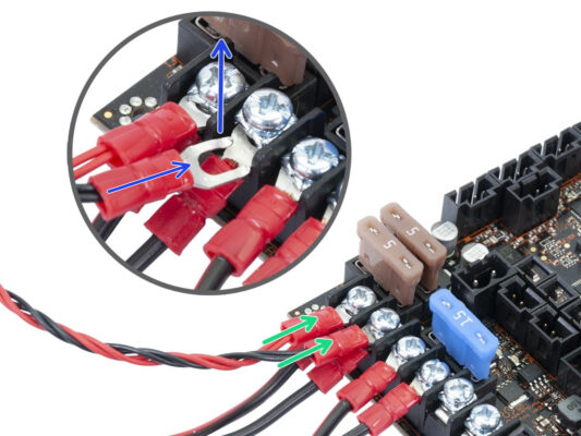
Connect the Power cable fork connectors.

First, loosen the screws on the terminals so that there is enough space.

Stack the MMU power connectors on top of the the PSU cable connections in the first two clamps on the left side of the Einsy board.

The power cable connector "fork" has bent ends. Make sure they point up. See the picture for a reference.
Red (+ / positive) wire goes into the first slot.

Black (- / negative) wire goes into the second slot.
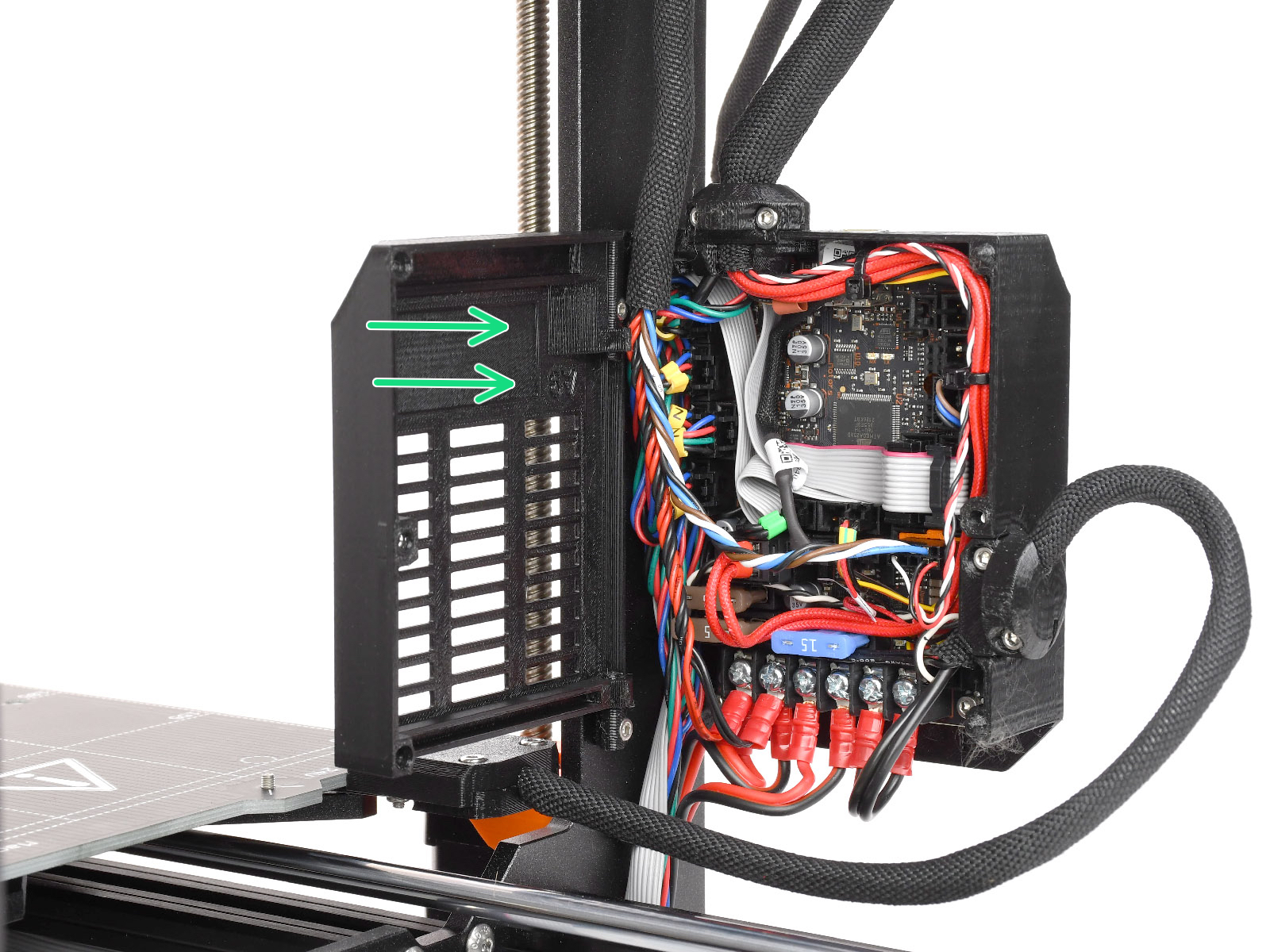
¡Aprieta los cables de alimentación firmemente!
Confirm that the cables are connected in the correct order to avoid causing damage to the device.
MK3S+ Closing the electronics box
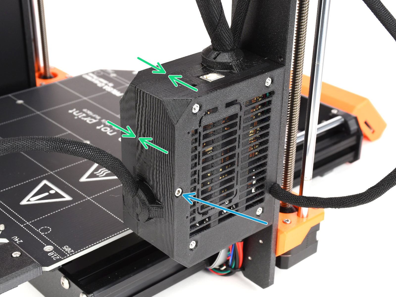
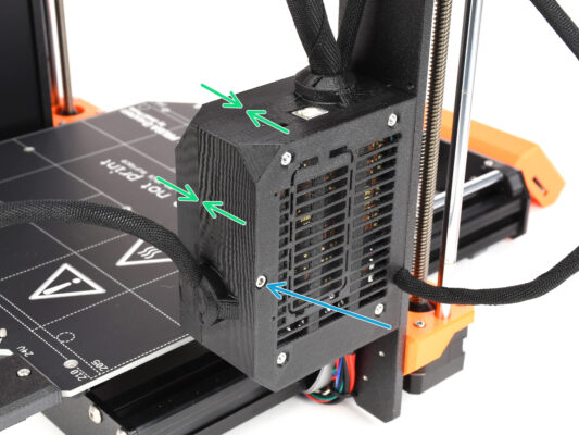
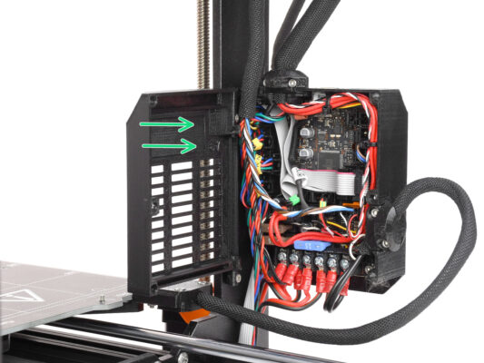
Close the door. Make sure no wire is being pinched while you close the door.
Tighten up the M3x40 screw from the other side to lock the door.
Software Download
Software Download
Software Download
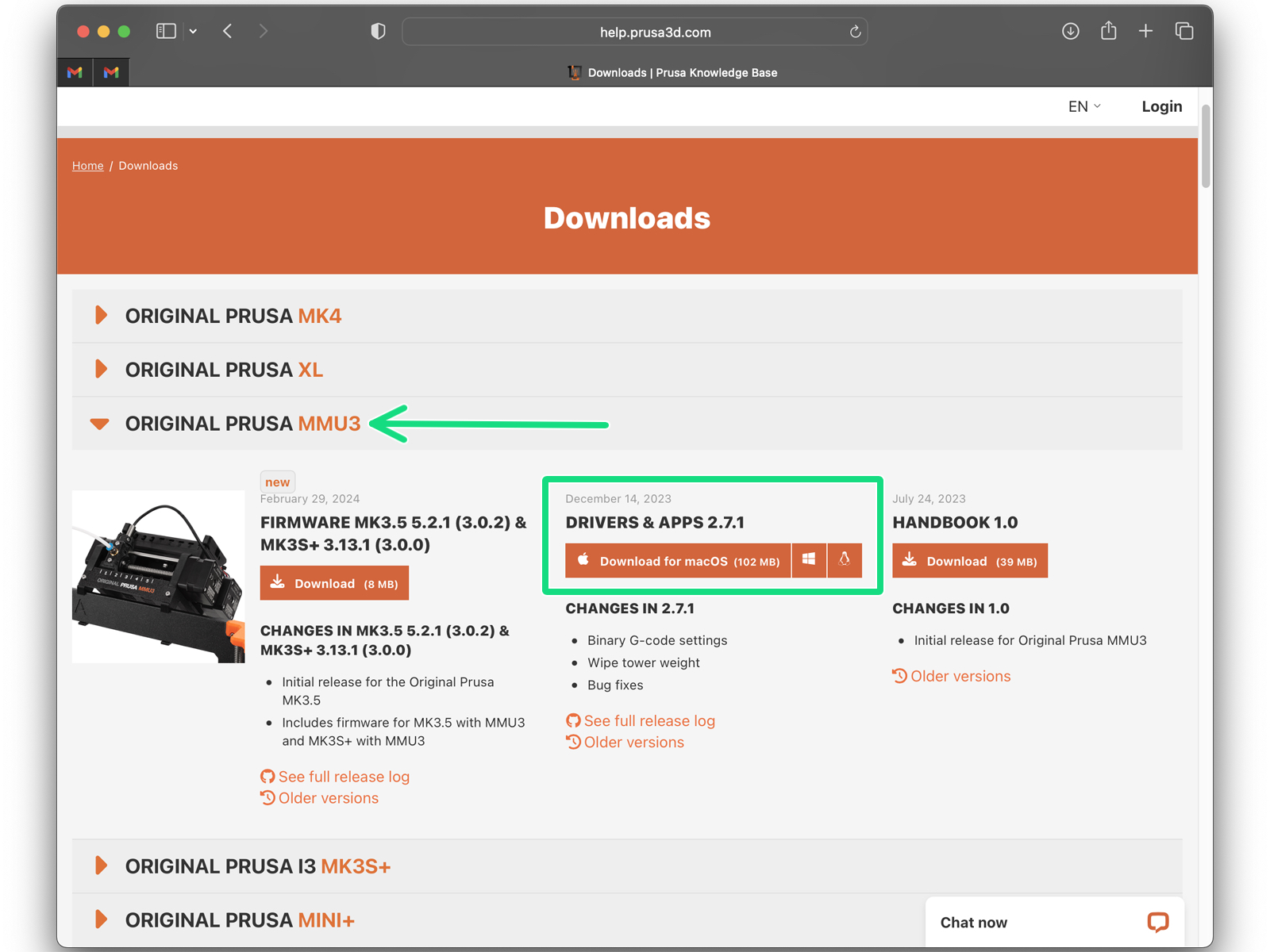
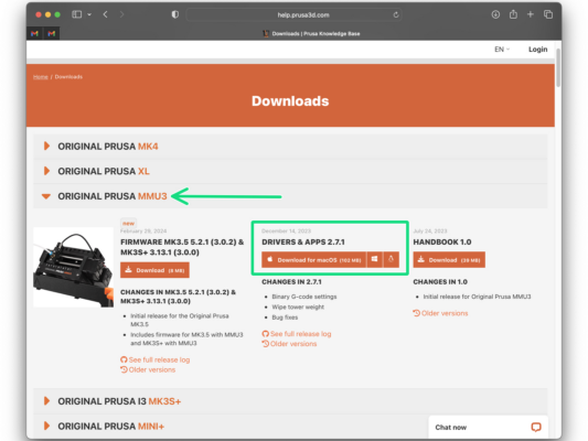
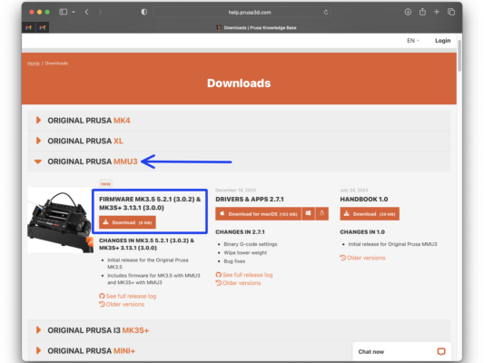
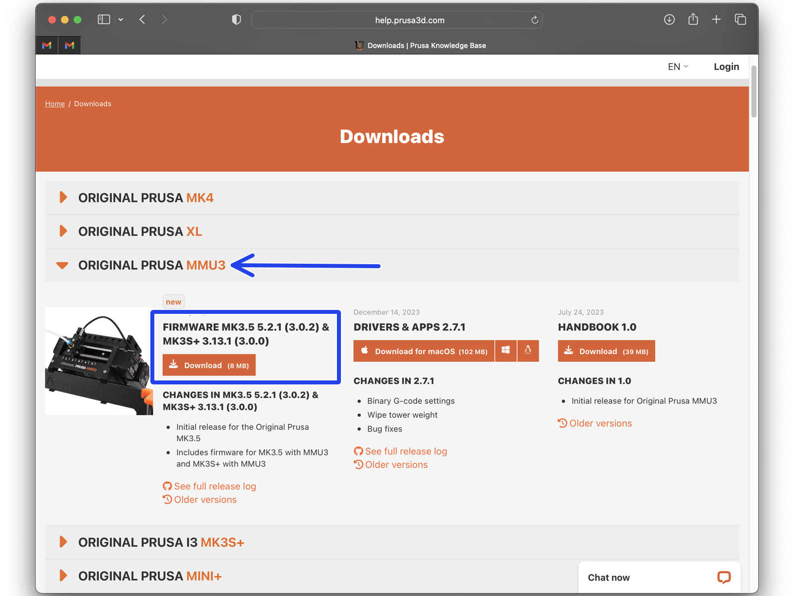
Busca la ORIGINAL PRUSA MMU3en la lista. Em la sección Drivers y Apps, descarga el último paquete.
¡Deja esta página abierta para los siguientes pasos!
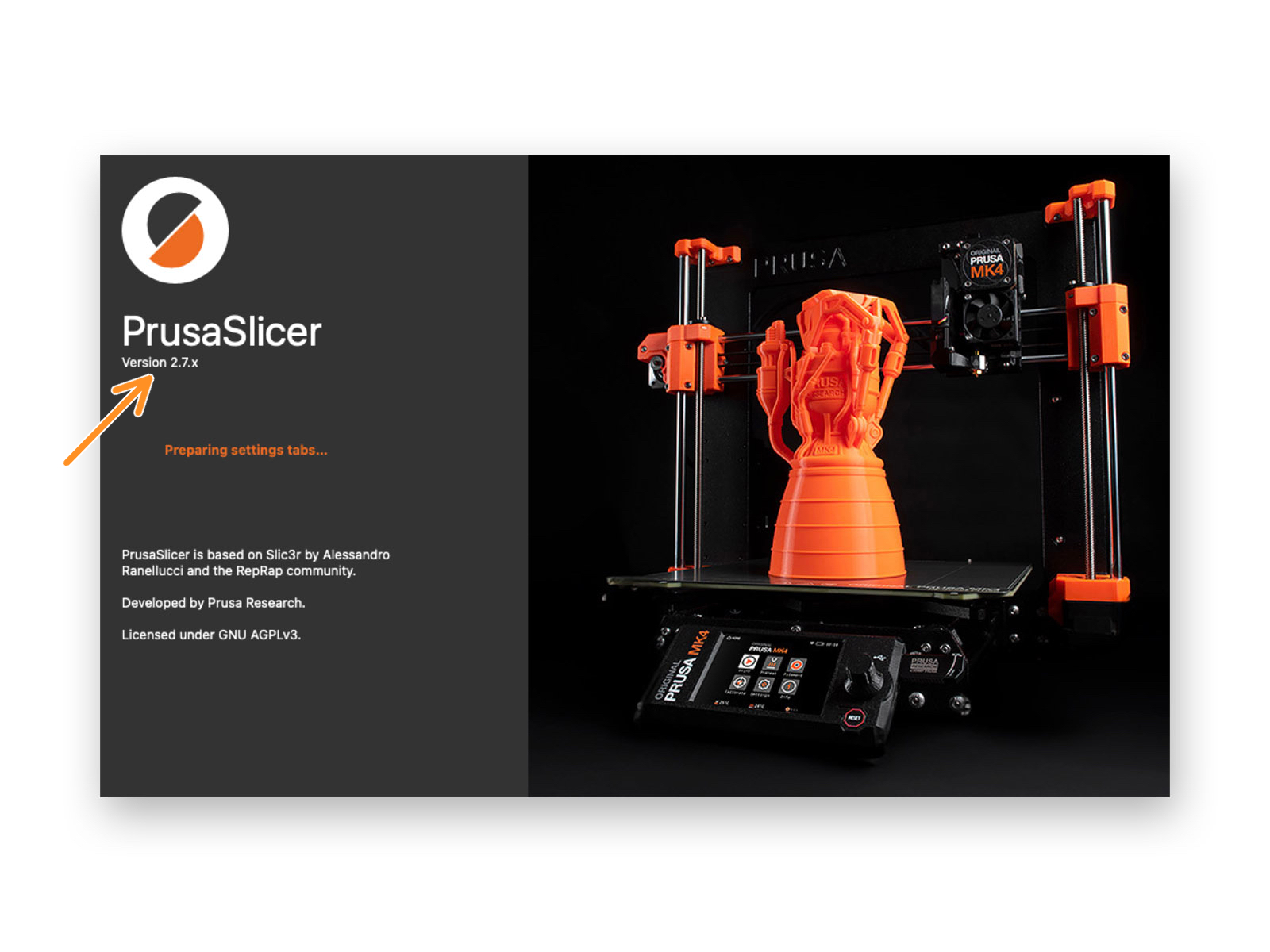
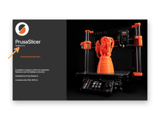
Instala el paquete en su ordenador y abre el PrusaSlicer.
La app de PrusaSlicer es parte del paquete de controladores. Incluye la herramienta de actualización del firmware. El paquete de controladores también incluye objetos de muestra para imprimir.
PrusaSlicer setup for MMU3
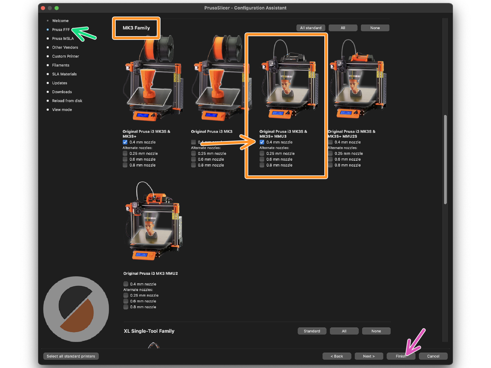
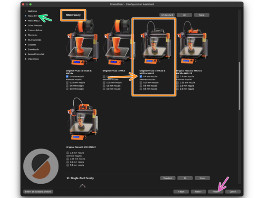
Open the PrusaSlicer Assistant / Wizard. (Configuration > Configuration Assistant > Prusa FFF)

Desplázate hasta Familia MK3 y asegúrate de que la opción de la impresora correspondiente + MMU3 está seleccionada, dependiendo del modelo de impresora que tengas.
The default nozzle is 0.4mm from factory.
Click Finish to close the Wizard.
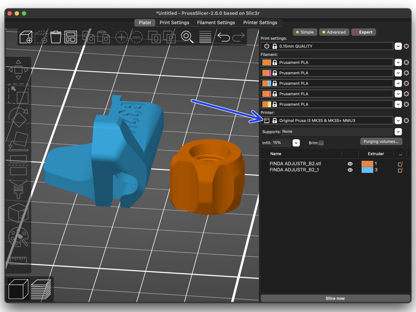
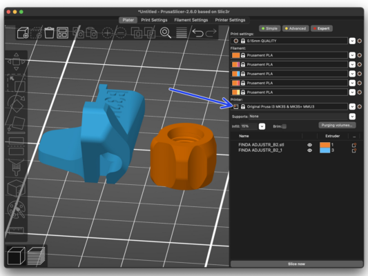
En el menú Impresora:, selecciona el perfil de impresora MMU3 para los laminados futuros.
Ten en cuenta que la MMU3 en la MK3S+ es compatible con el antiguo perfil MMU2S de Slicer y los códigos G, ¡pero no con los perfiles del MMU2!
Firmware files download

Deberás actualizar tanto el firmware de la impresora como el de la unidad MMU. Utiliza únicamente una combinación de las versiones de firmware más recientes para ambos dispositivos juntos.
Please refer to the MMU3 Firmware Compatibility article to find out exactly which firmware version you need.
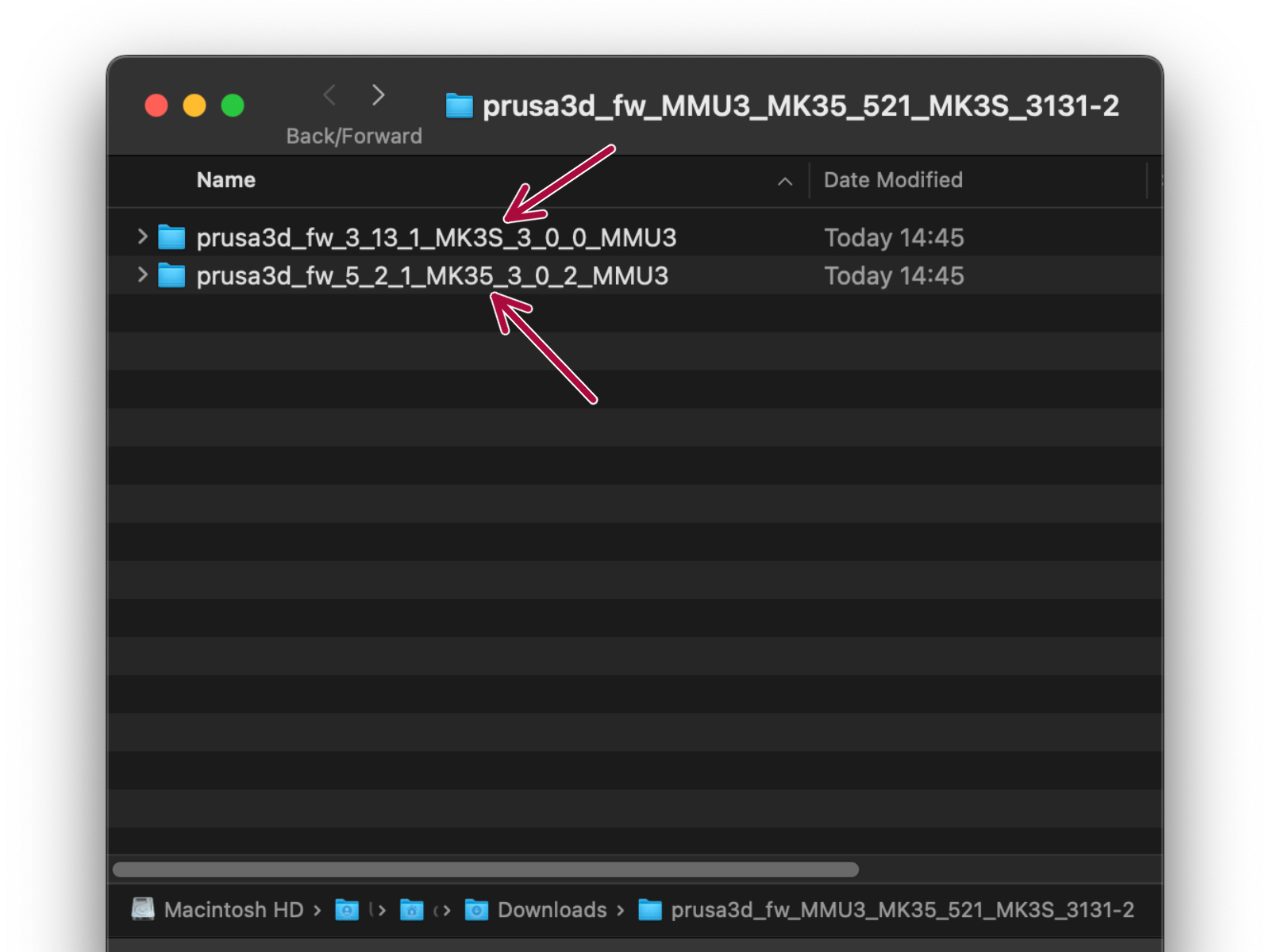
Go back to the help.prusa3d.com/downloads
Find the ORIGINAL PRUSA MMU3 on the list. Download the latest FIRMWARE file bundle.
Selecting a Printer firmware file
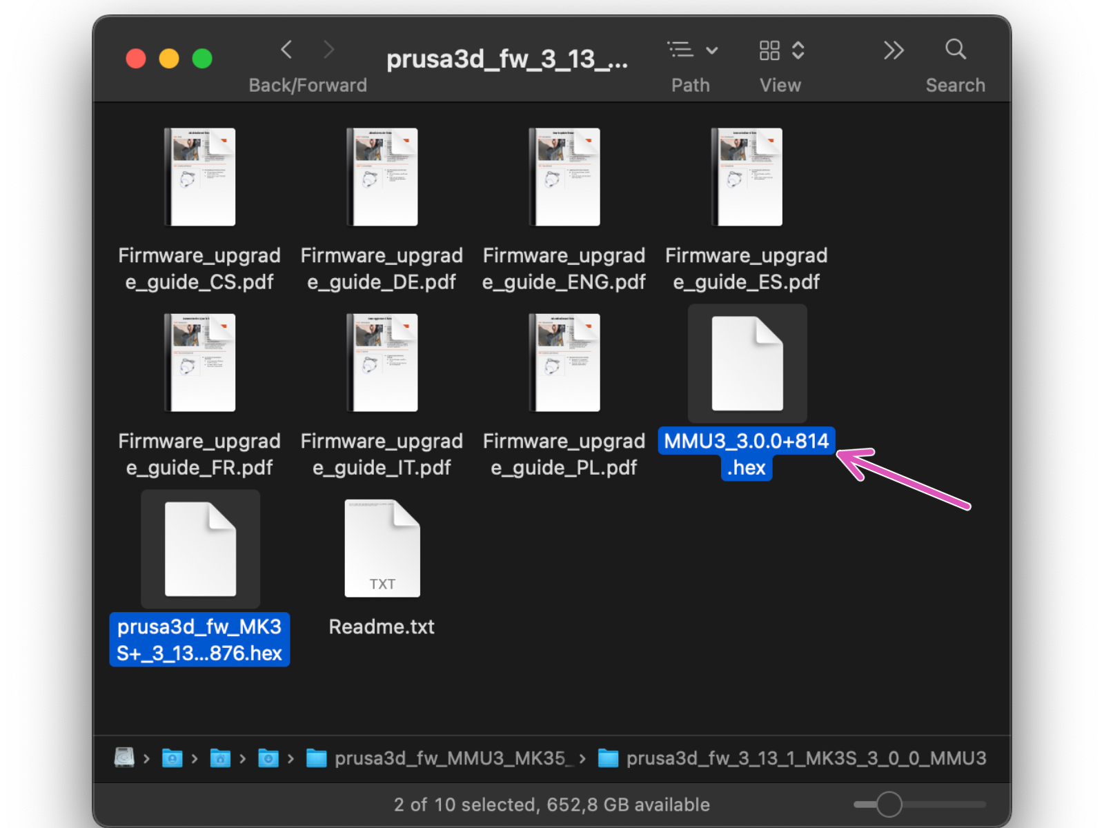
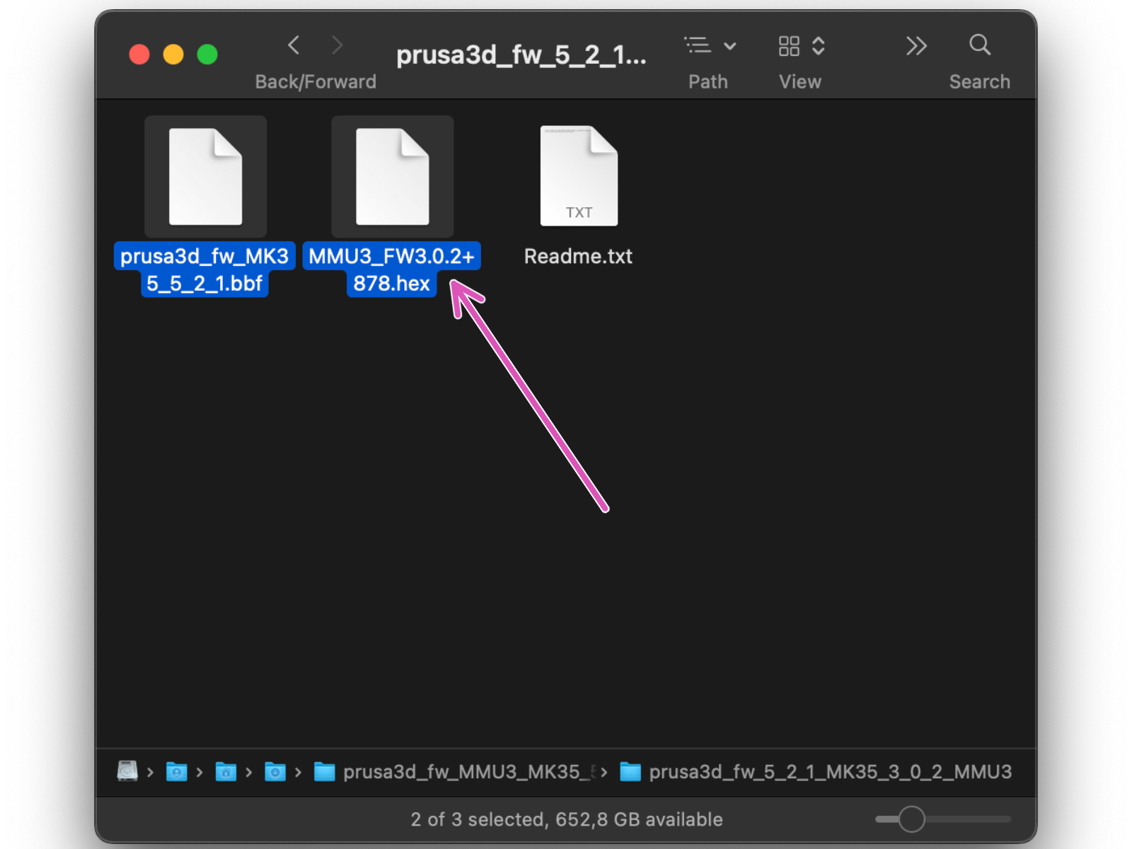
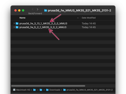
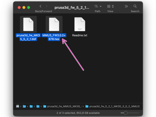
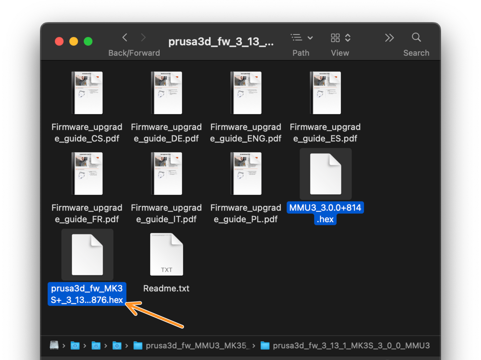
Abre el paquete de firmware que has descargado anteriormente. Abre una de las carpetas en función del modelo de impresora que tengas (selecciona "MK3S" para el modelo de la MK3S+)
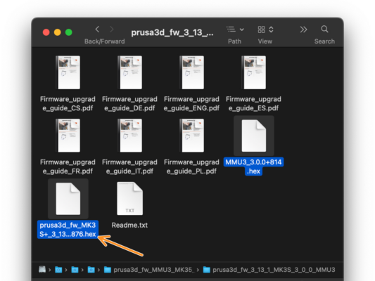
There are two firmware files in the folder. One for the printer, the other one for the MMU unit.
As a firmware file for the MK3S+, select the MK3S+  .hex file
On MK3S+ printer, MMU3 requires printer firmware 3.13 or newer!
If you are updating from a printer firmware 3.11 or older, the printer will require you to do a thermal model calibration first.
Flasheo Firmware MK3S+ (parte 1)
Connect the printer to the electricity and turn it on.

Now, let’s flash the printer’s firmware.

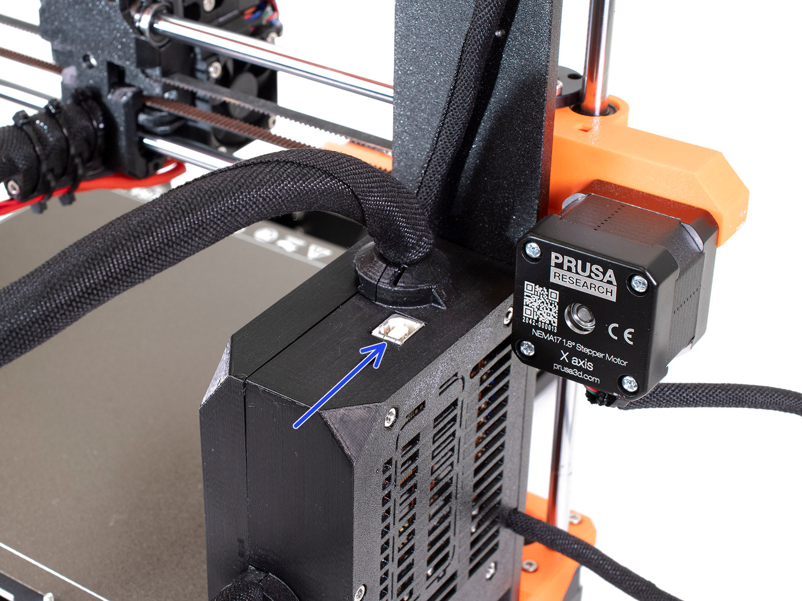
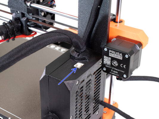
To flash the MK3S+, use the bundled USB Type B cable to connect the computer to the top of the black electronics box on the printer.
Then, continue to the next step.
MK3S+ Firmware flashing (part 2)
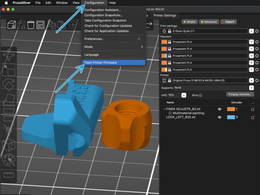
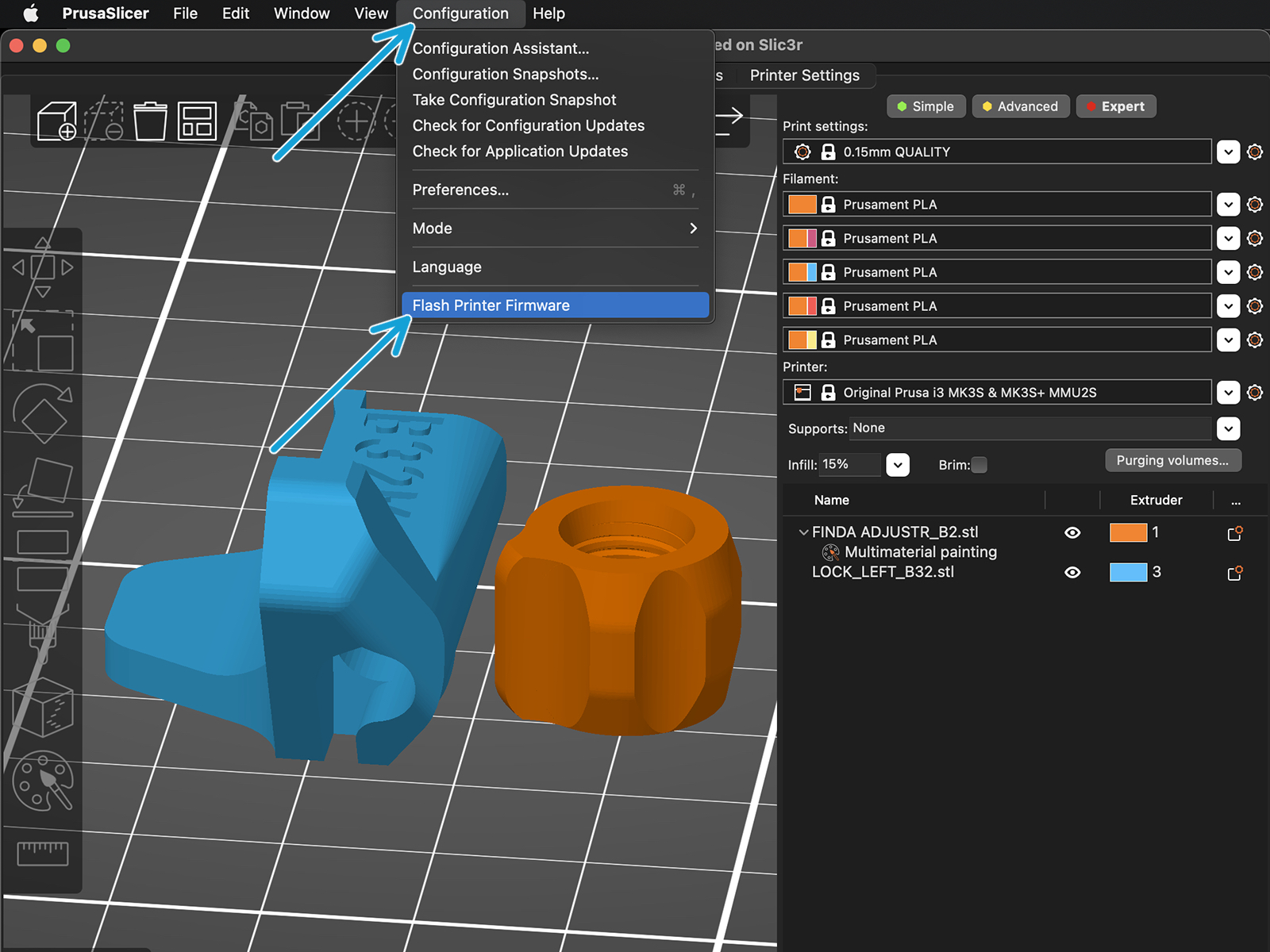
Abre PrusaSlicer y selecciona Configuración ->Flashear Firmware Impresora en el menú superior.
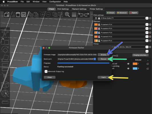
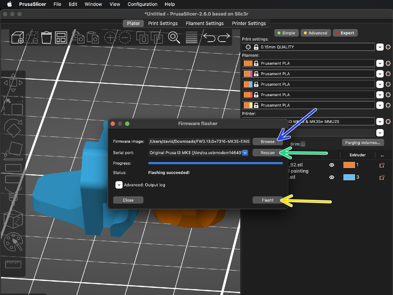
First, select the printer's firmware file on your computer.
(e.g. FW3.13.0-MK3S-EINSY10a_MULTILANG.hex)
Hit Rescan to make sure your printer appears in the Serial port: column
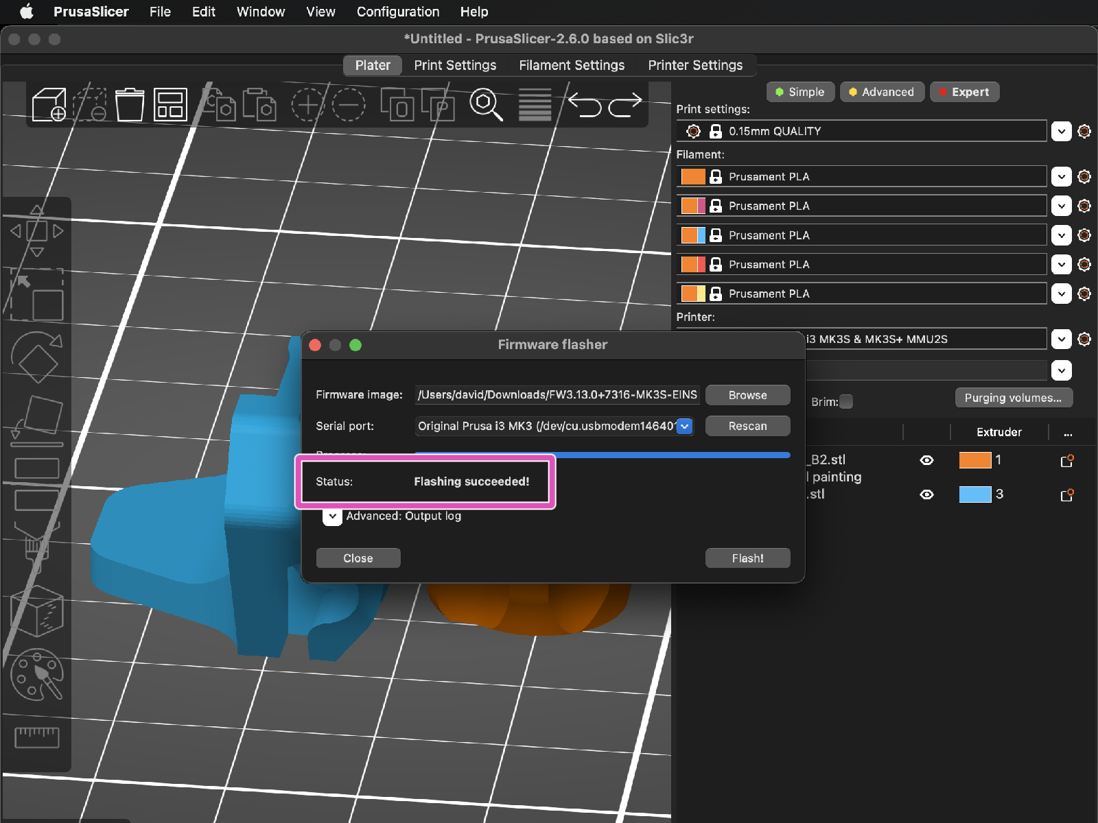
Presiona el botón de Flashear.
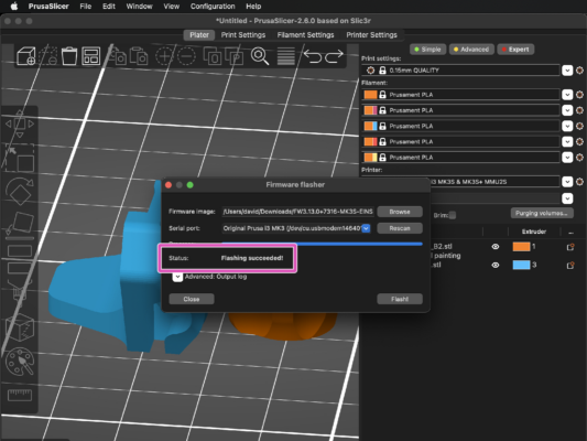
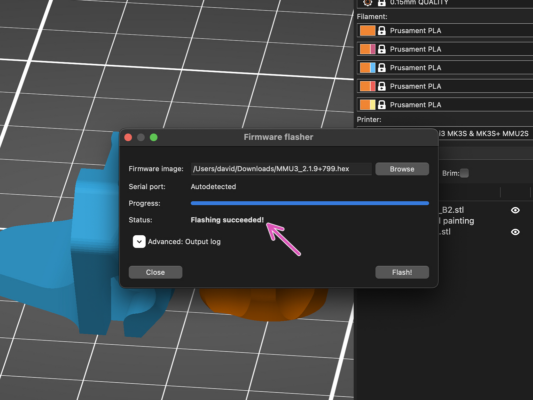
Wait until you see the Flashing succeeded message.
En caso de que tengas problemas al instalar el firmware, por favor visita el artículo para solucionar problemas.
Encendido y reinicio de la MMU MK3S+
After finishing the firmware update, make sure there are no filaments loaded neither in the extruder, or in the MMU unit.

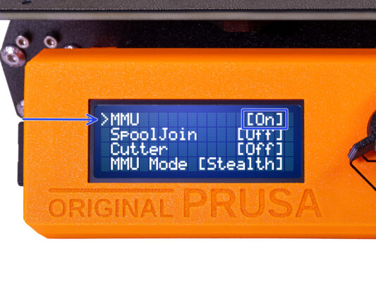
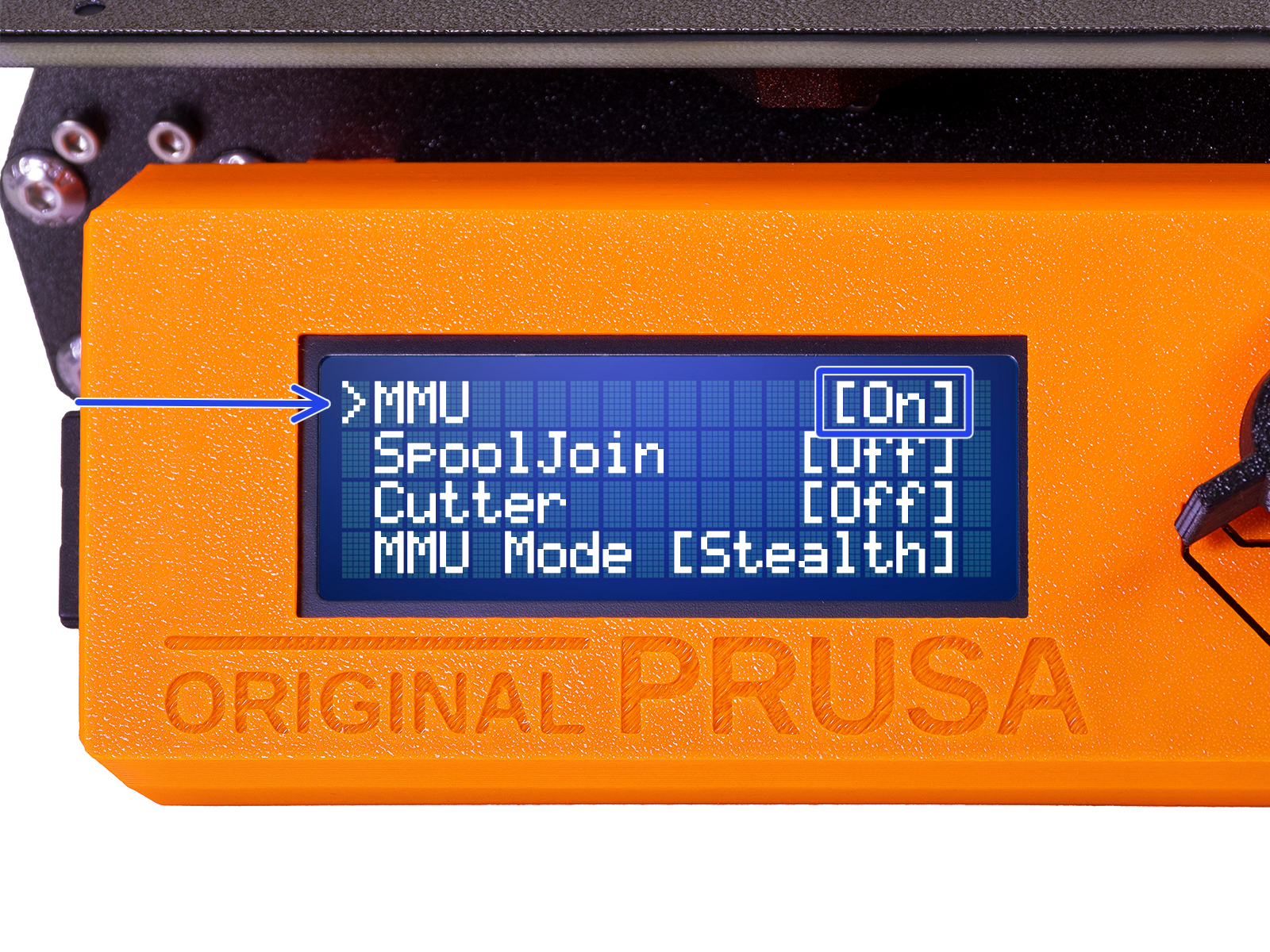
Navigate to the LCD menu > Settings > MMU

and make sure it is set to MMU [On]
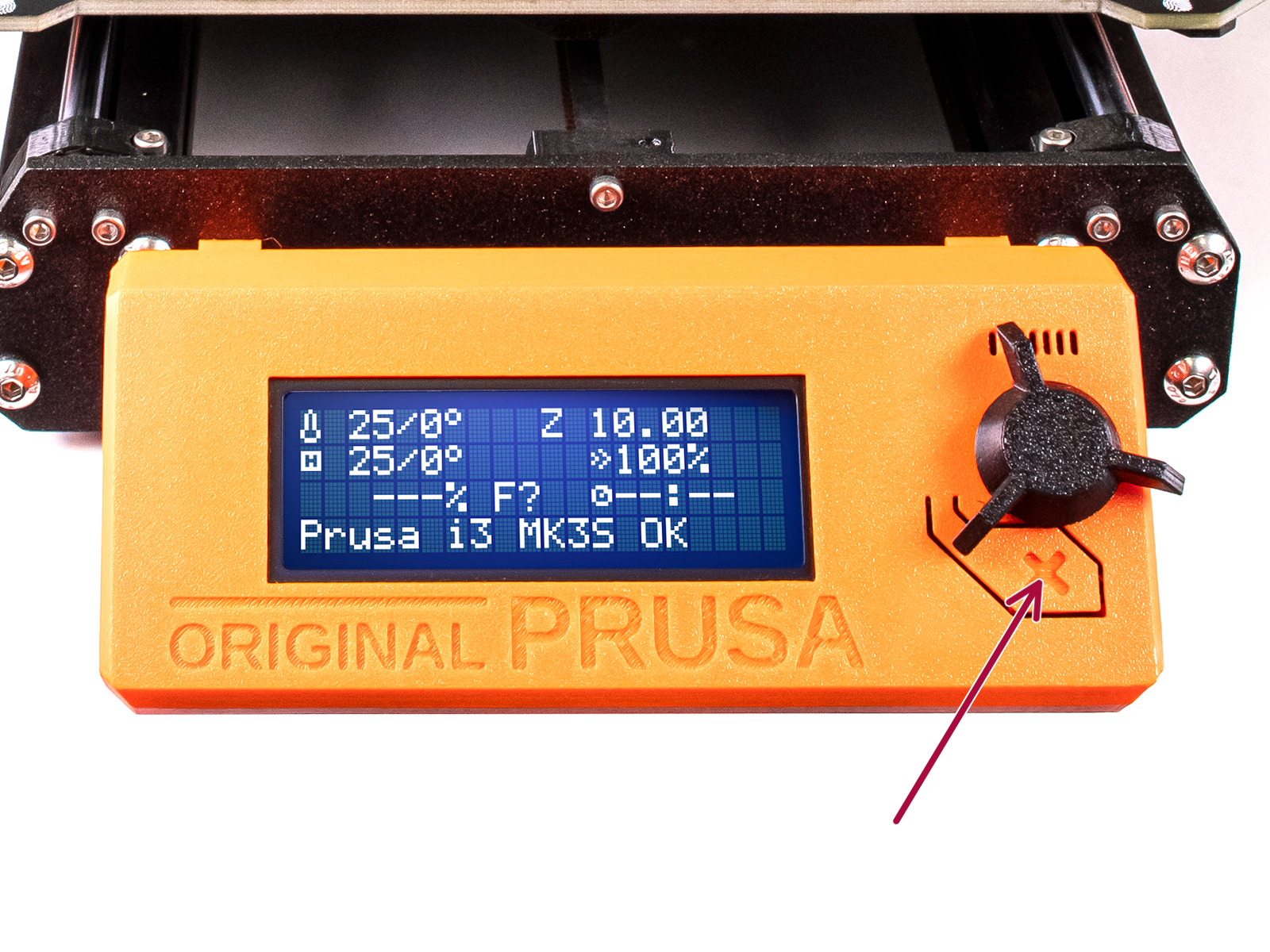
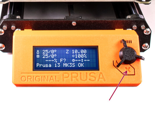
Pulsa el botón de reinicio en la caja LCD de la impresora.
From now on, the reset button on the printer resets also the MMU unit. Wait for a while, the MMU unit will go through the self-test routine. (accompanied by flashing LED lights on the MMU unit) Wait until it boots up properly, before issuing any commands to the printer.
In case of necessity, the reset button is also useful to help you get out of some unrecoverable situations even for the MMU unit. But remember, it also aborts an ongoing print immediately.
MMU3 Firmware flashing (part 1)
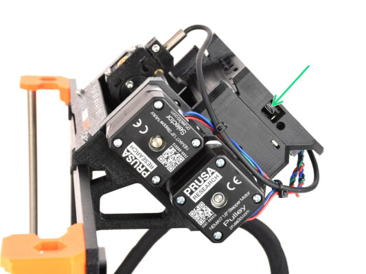
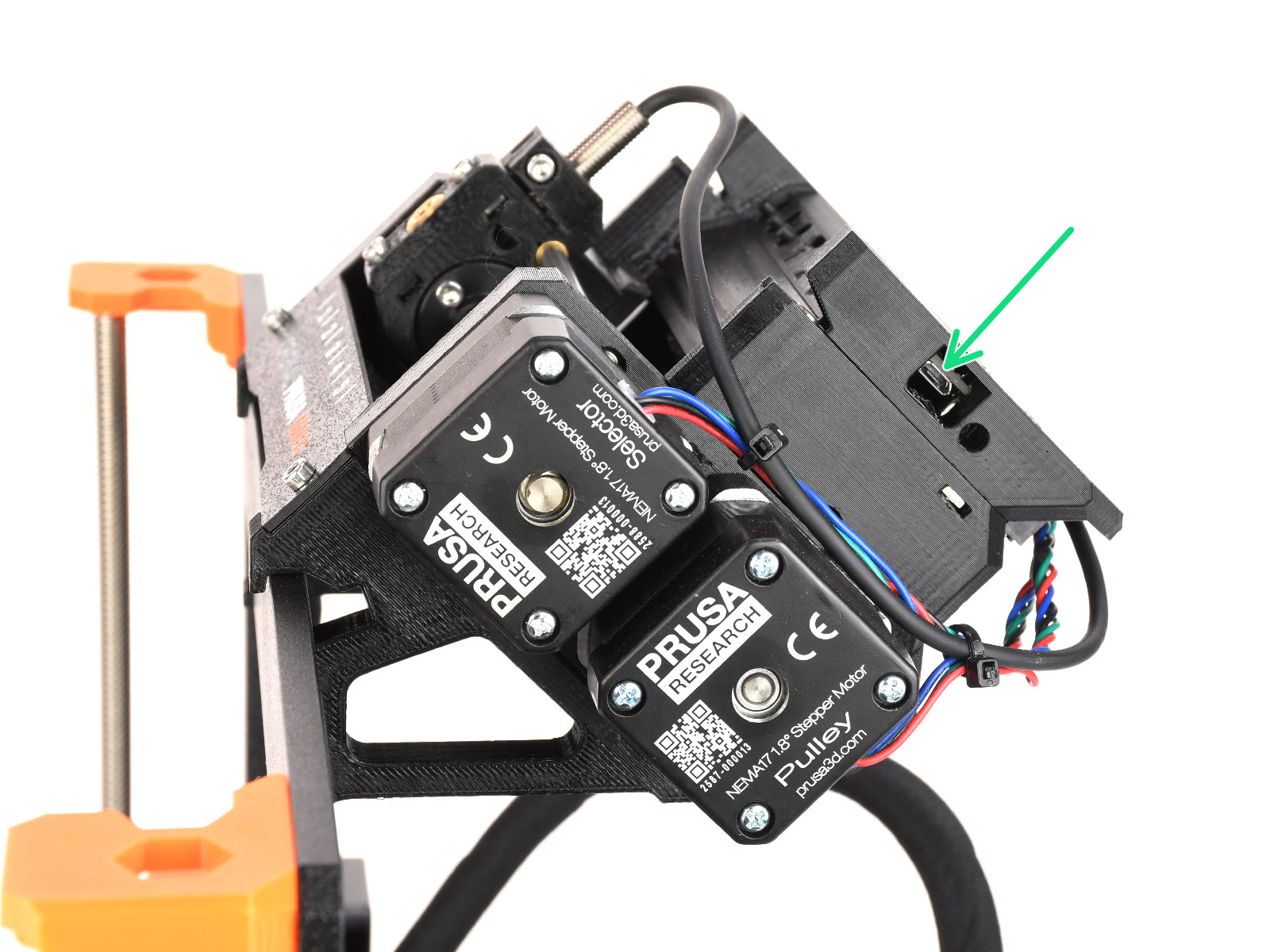
The MMU3 firmware file needs to be flashed into the MMU unit itself. Find the microUSB connector on the right side of the MMU3 unit.
Connect the unit to your computer using the bundled microUSB cable.
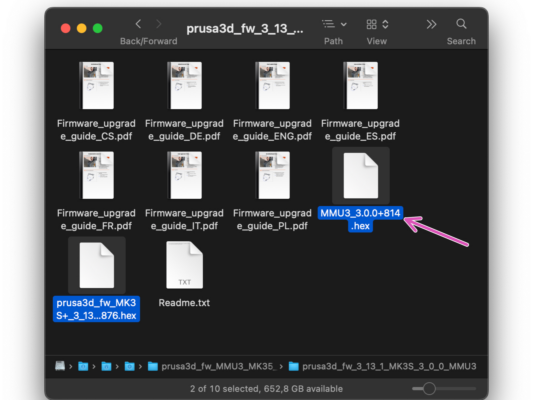
On your computer, select the appropriate MMU firmware file compatible with your printer model.
MMU3 Firmware flashing (part 2)
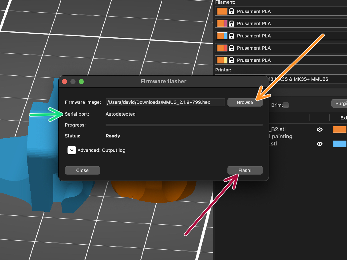
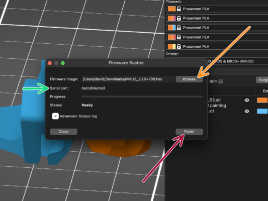
Abre PrusaSlicer y selecciona Configuración ->Flashear Firmware Impresora en el menú superior.
Haz clic en Buscar y selecciona el archivo de imagen del firmware MMU3 en tu ordenador.
(por ejemplo MMU3_3.0.0.hex)
El puerto serie debería detectarse automáticamente.
Presiona el botón de Flashear.
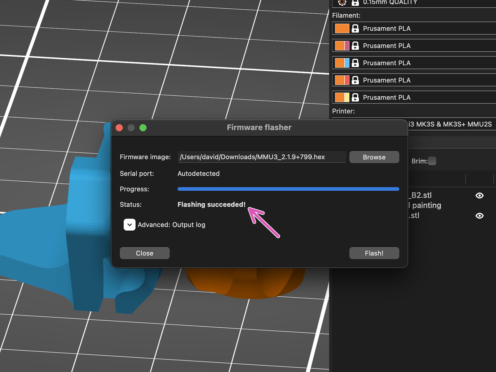
Espera hasta que aparezca el mensaje ¡Exito al flashear!.
Una vez finalizado el flasheo, desconecta el cable USB.
En caso de que tengas problemas al instalar el firmware, por favor visita el artículo para solucionar problemas.
IR filament sensor calibration (Part 1)
In the following steps, we will calibrate the IR Filament sensor iside the Chimney on the extruder. Follow the instructions carefully, this part is very important!
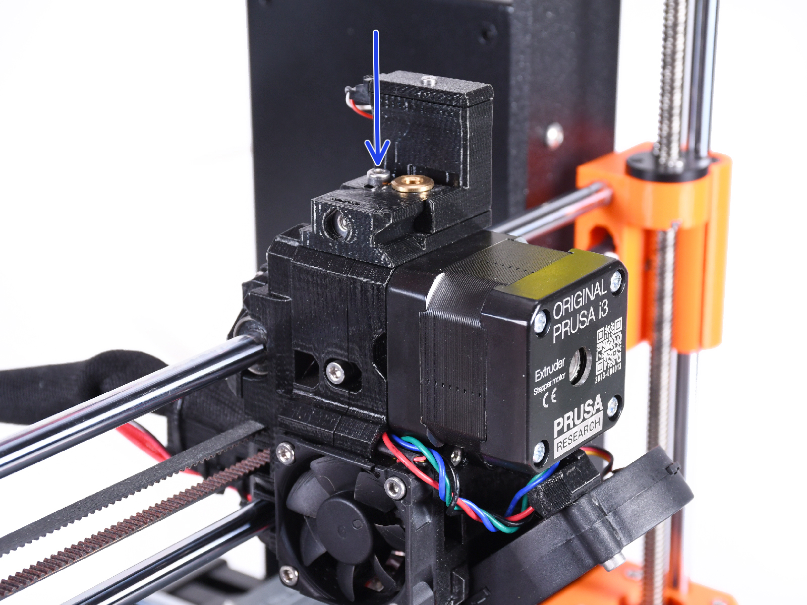
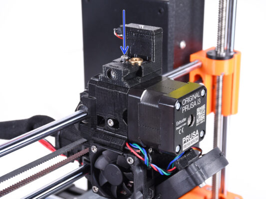
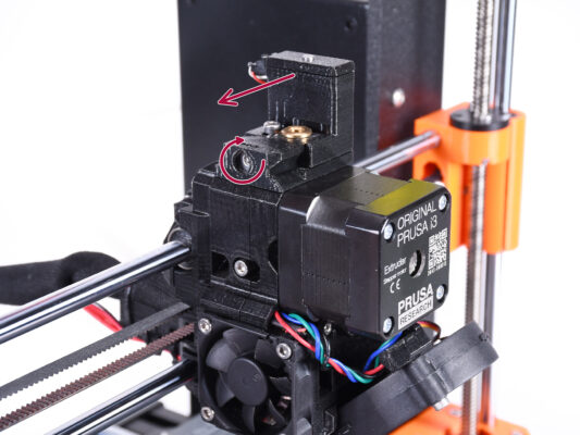
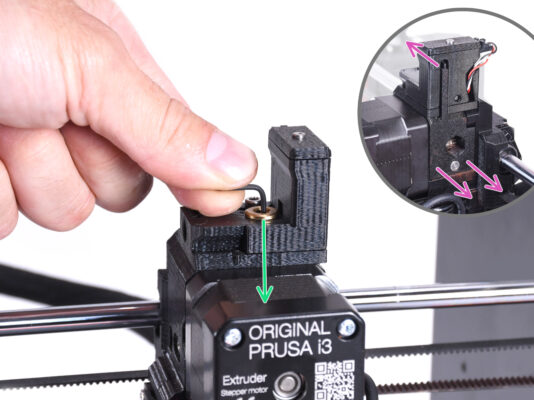
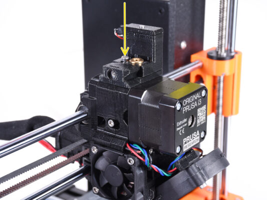
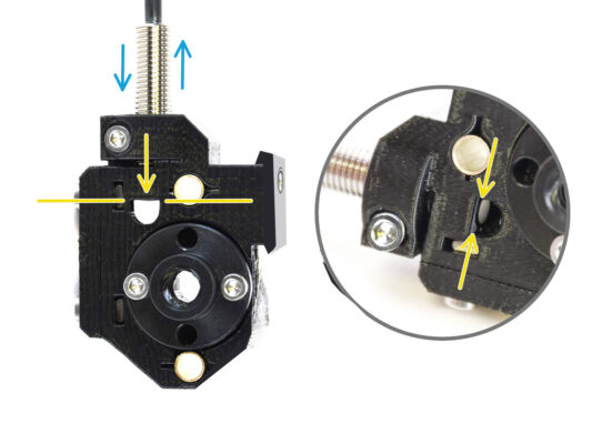
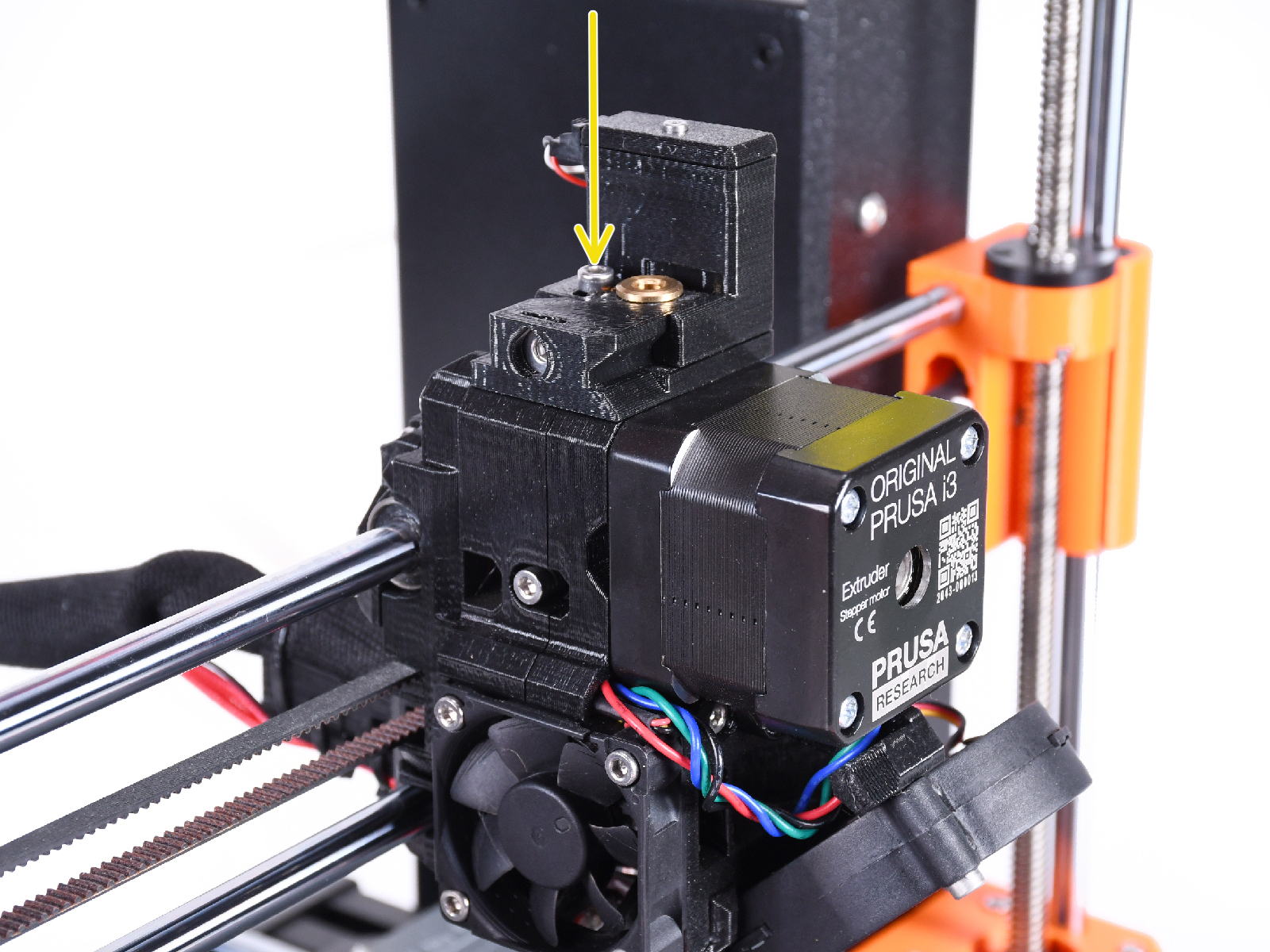
Con una llave Allen de 2.5mm, asegúrate de que el tornillo prisionero de la Chimenea no esté apretado. No lo quites del todo. Mantiene unida la chimenea.
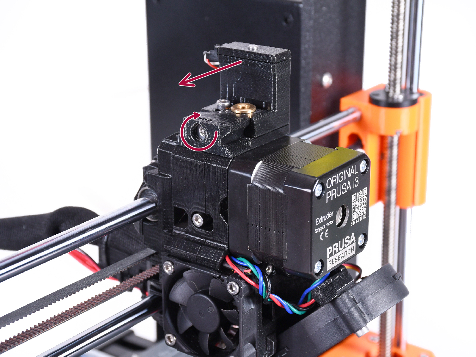
Apriete con cuidado el tornillo de calibración lateral para que la chimenea se desplace completamente hacia la izquierda.

Al apretar el tornillo de calibración, la chimenea se desplaza hacia la izquierda, haciéndola menos sensible a la activación.
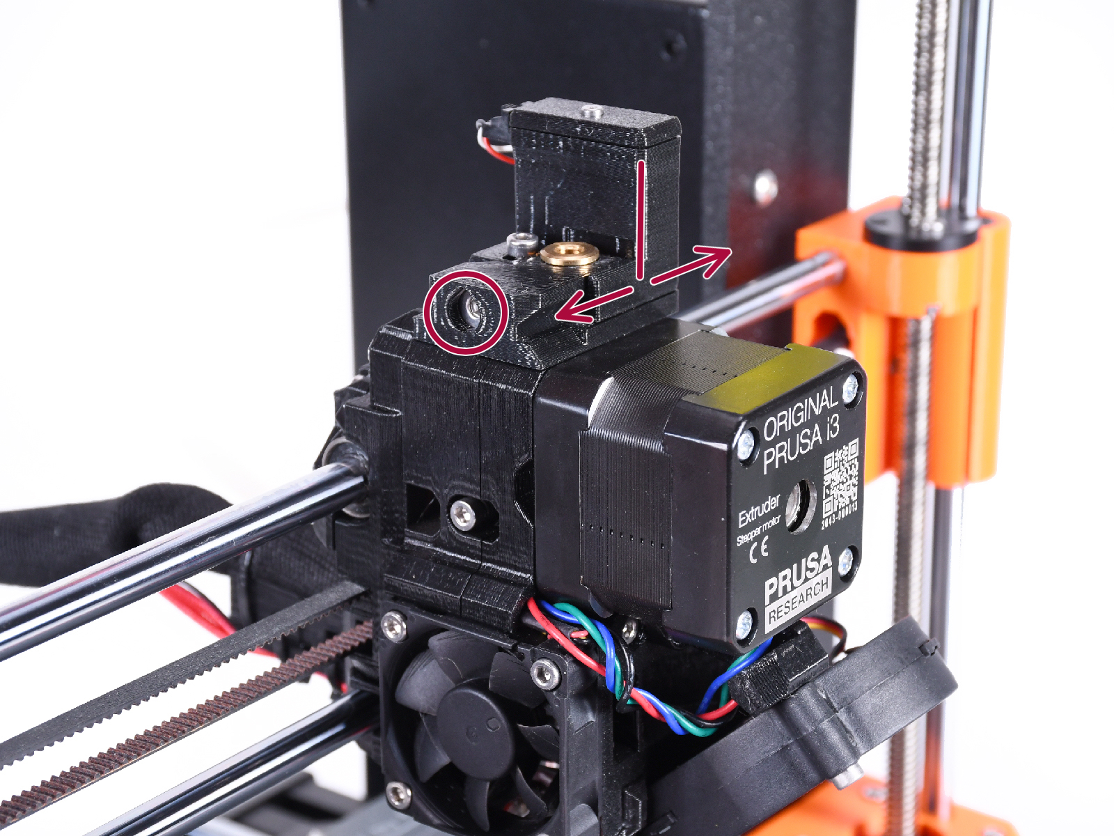
Al aflojar el tornillo de calibración, la chimenea se desplaza hacia la derecha, haciéndola más sensible a la activación.
Tighten the calibration screw until the chimney moves all the way to the left.
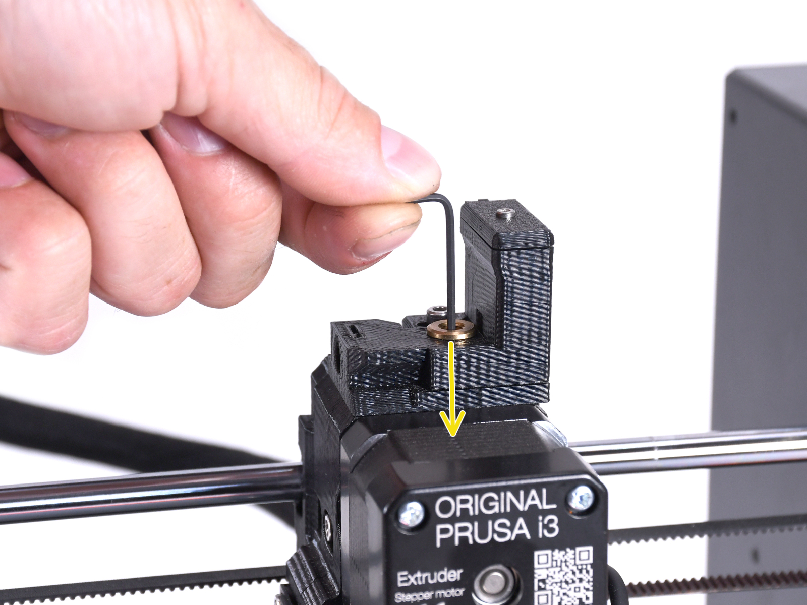
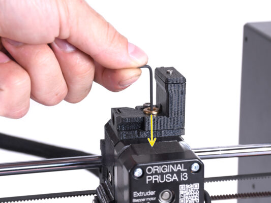
Inserta una llave Allen de 1.5mm en el extrusor. No la empujes hasta el fondo todavía.
Make sure you are using the thinnest of the bundled Allen keys; 1.5mm. Do not use the 2mm one!!
IR filament sensor calibration (Part 2)

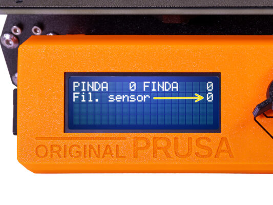
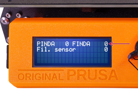
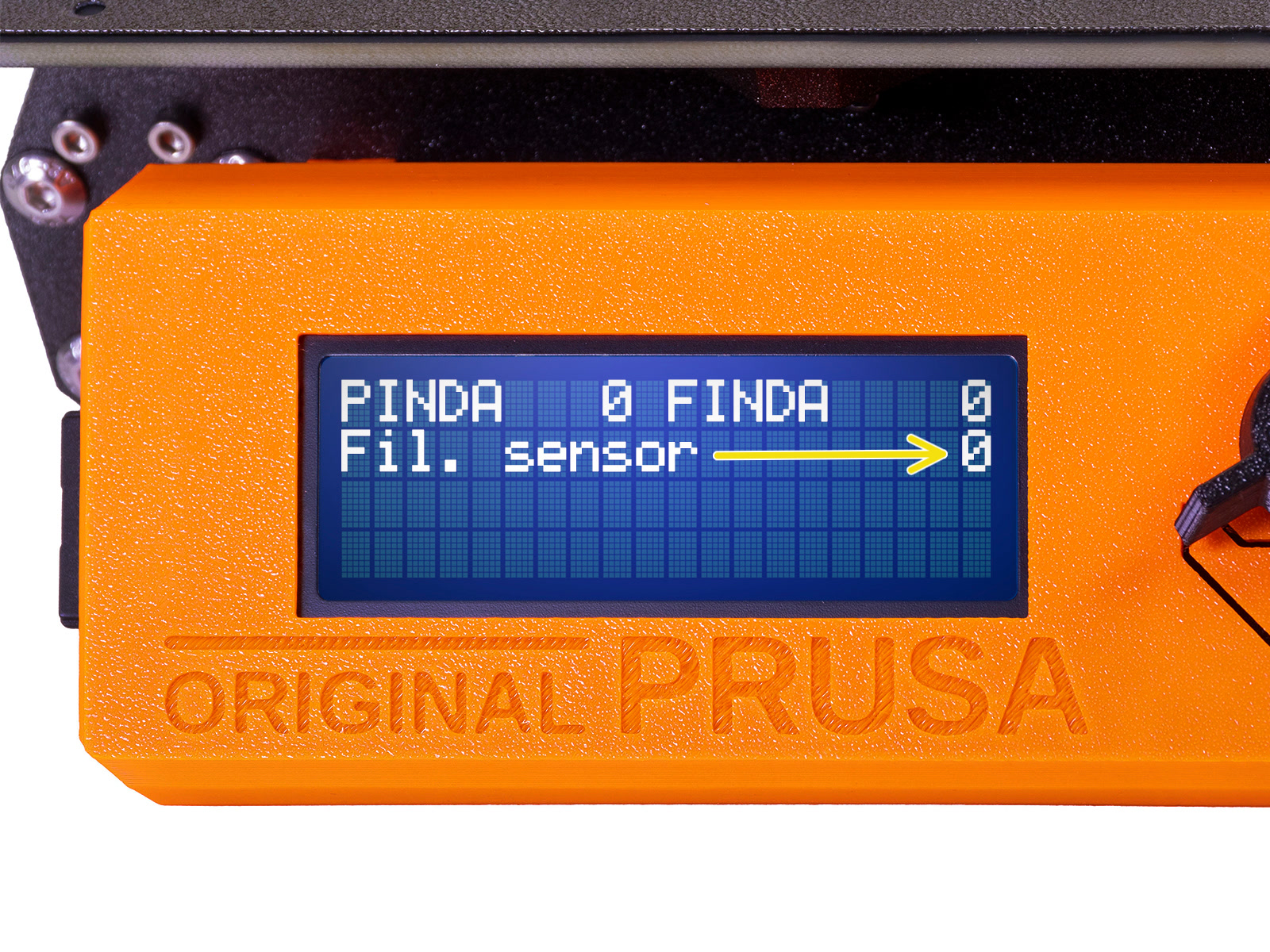
Ve a Menu > Soporte > Info sensor > Sensor Fil. en tu MK3S+

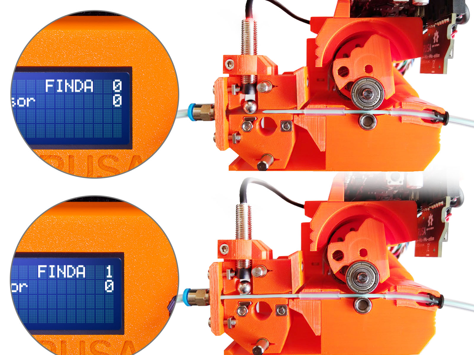
El sensor Fil. debe indicar el valor 0 / NINS cuando la llave Allen no está presionada hasta el fondo para que la puerta tensora no esté inclinada hacia fuera.

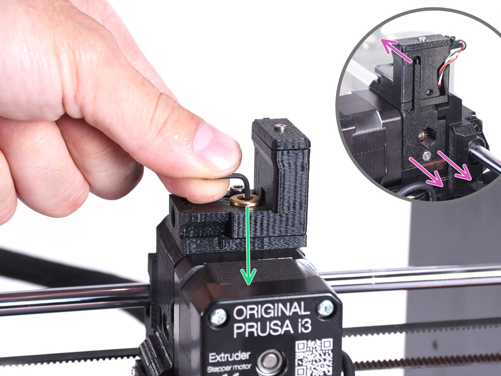
Ahora empuja la llave Allen de 1.5mm hacia abajo hasta que toque los engranajes Bondtech.
(no temas hacer fuerza hacia abajo para colocar la llave entre los engranajes)

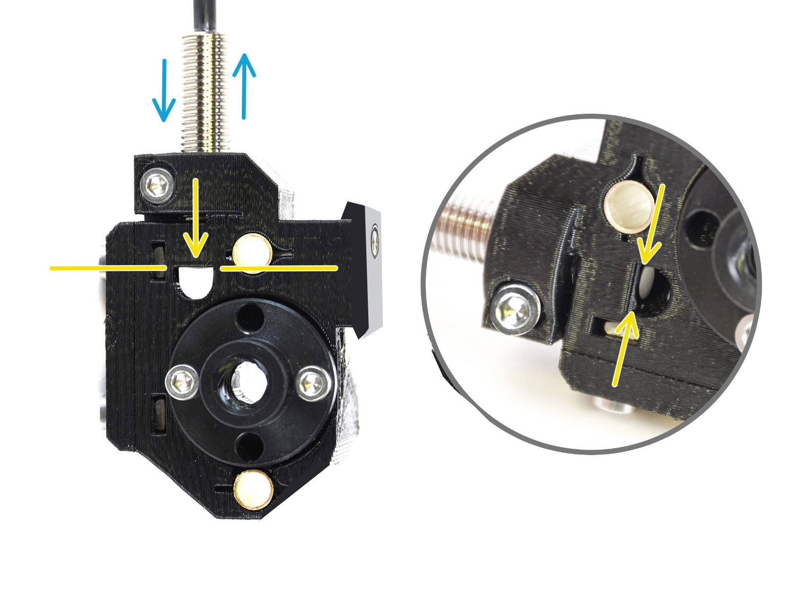
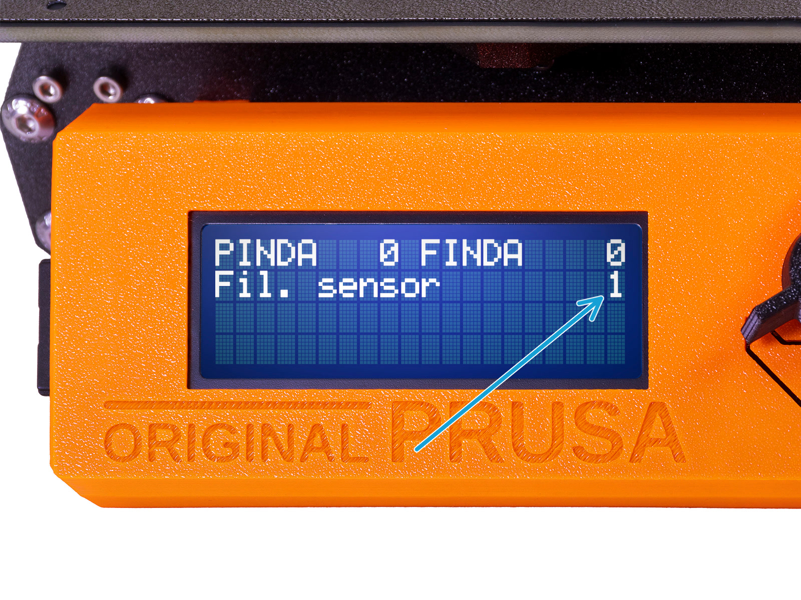
La puerta del rodillo tensor a la derecha del extrusor debe inclinarse ligeramente hacia fuera simulando un filamento insertado.

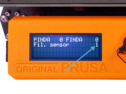
La línea Fil. sensor: en la pantalla LCD debería indicar el valor 1 con la llave Allen (o un filamento) introducido. Sigue soltando el tornillo de calibración hasta que haya número 1 en la pantalla LCD.

Luego, aflójalo otra media vuelta.

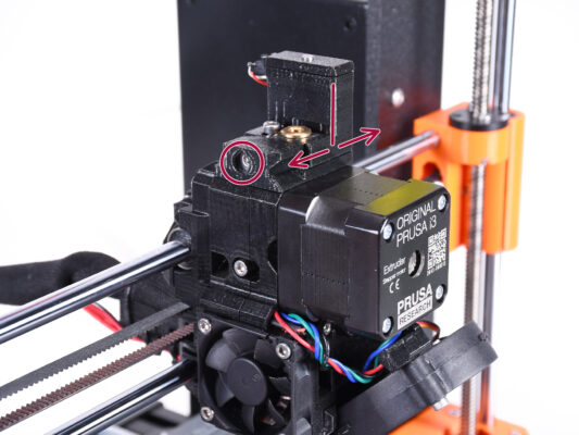
By rotating the calibration screw, we need to fine-tune the chimney position so that the number on the LCD reliably changes when inserting and removing the Allen key or filament from the Bontech gears.
IR filament sensor calibration (Part 3)
Calibrating the IR filament sensor is super-crucial in order for MMU3 unit to work properly!
Por favor, repite esta comprobación varias veces.
Confirma que el sensor funciona correctamente: Vuelve a ver la pantalla LCD si el número del sensor fil.
muestra 1 cuando la llave Allen (/filamento) se introduce hasta el final
o 0 cuando no se introduce hasta el final.
Cuando el sensor funcione de forma fiable y correcta, bloquea la chimenea apretando el tornillo de bloqueo desde arriba.
Después de apretar el tornillo, verifica que las lecturas en la pantalla LCD siguen siendo correctas al insertar y retirar la llave Allen.
Encontrará más información sobre la calibración del sensor IR de filamento en el artículo Procedimiento de calibración del sensor IR o en el capítulo 7.1 del Manual.
SuperFINDA sensor calibration info
Muy bien. Has calibrado tu sensor de filamento IR. Ahora, podemos pasar a calibrar el sensor SuperFINDA dentro del selector en la unidad MMU.
For factory-assembled MMU3 units, the SuperFINDA is pre-calibrated, so you can skip the calibration steps.
In the next step, we'll calibrate the sensor's position.
It is CRITICAL that both the filament sensor in the extruder and the SuperFINDA sensor function accurately. Otherwise, you will have trouble with the device.
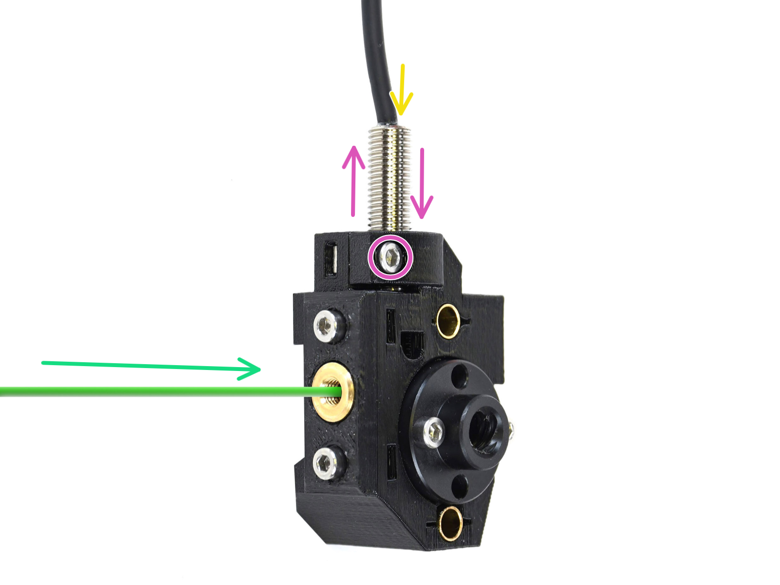
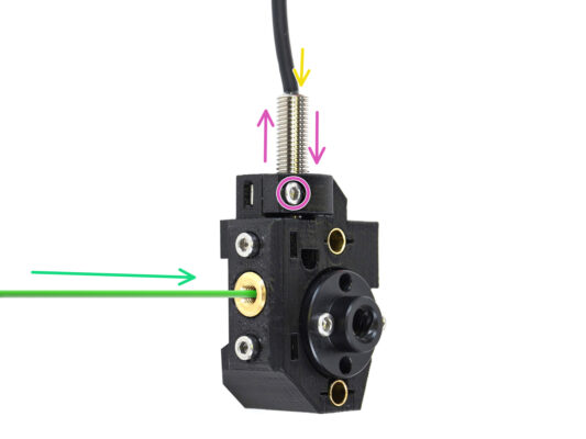
Use the inspection window on the selector to align the bottom of the sensor with the top of the window, as a starting point.
When filament is in the selector, the steel ball rises and should be detected by the SuperFINDA sensor. Ensure the distance between the ball and the sensor is perfectly calibrated.
SuperFINDA calibration
Coge un trozo de filamento con la punta afilada e introdúcelo en el selector a través de la abertura roscada de latón de la parte delantera.
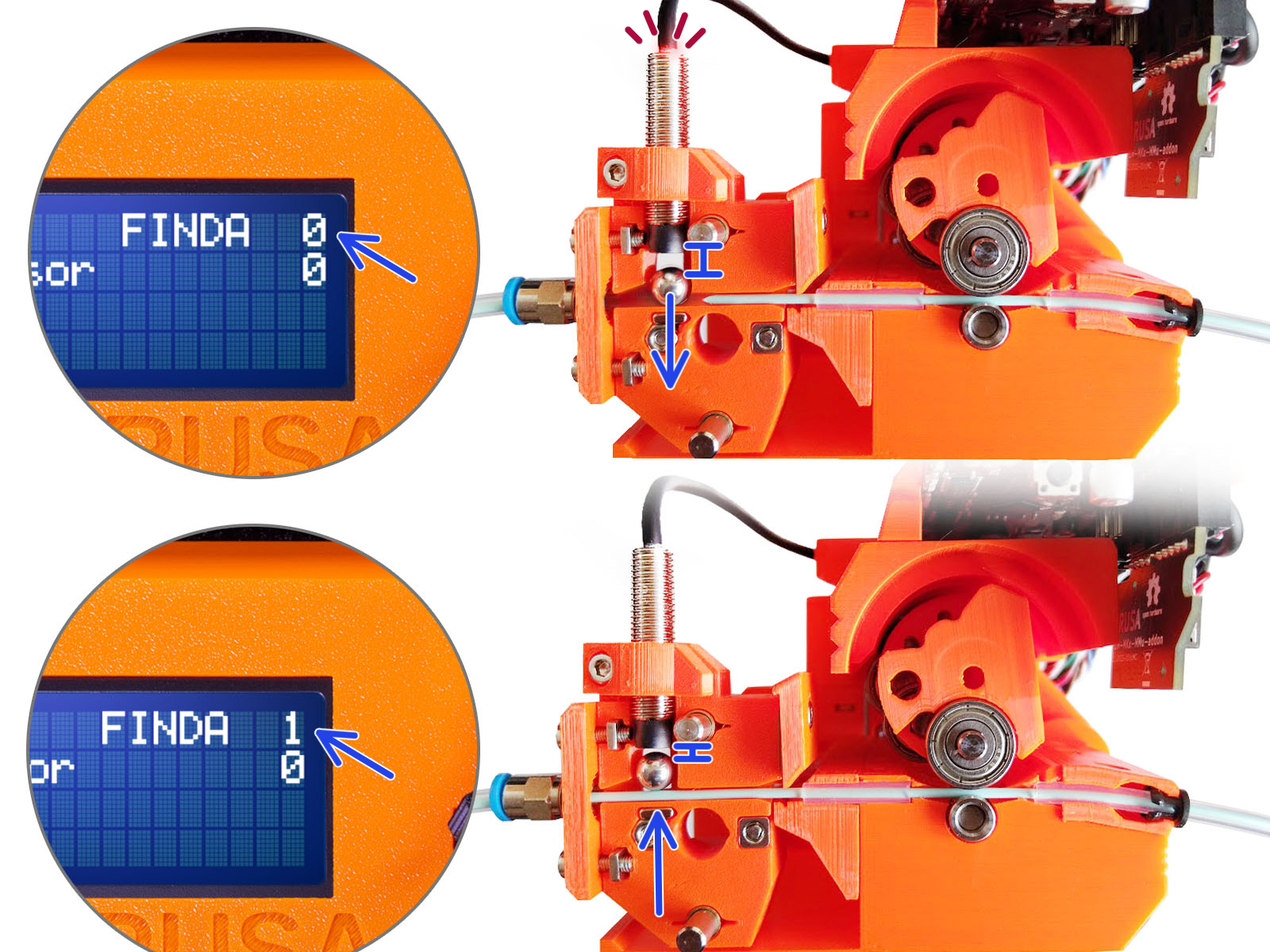
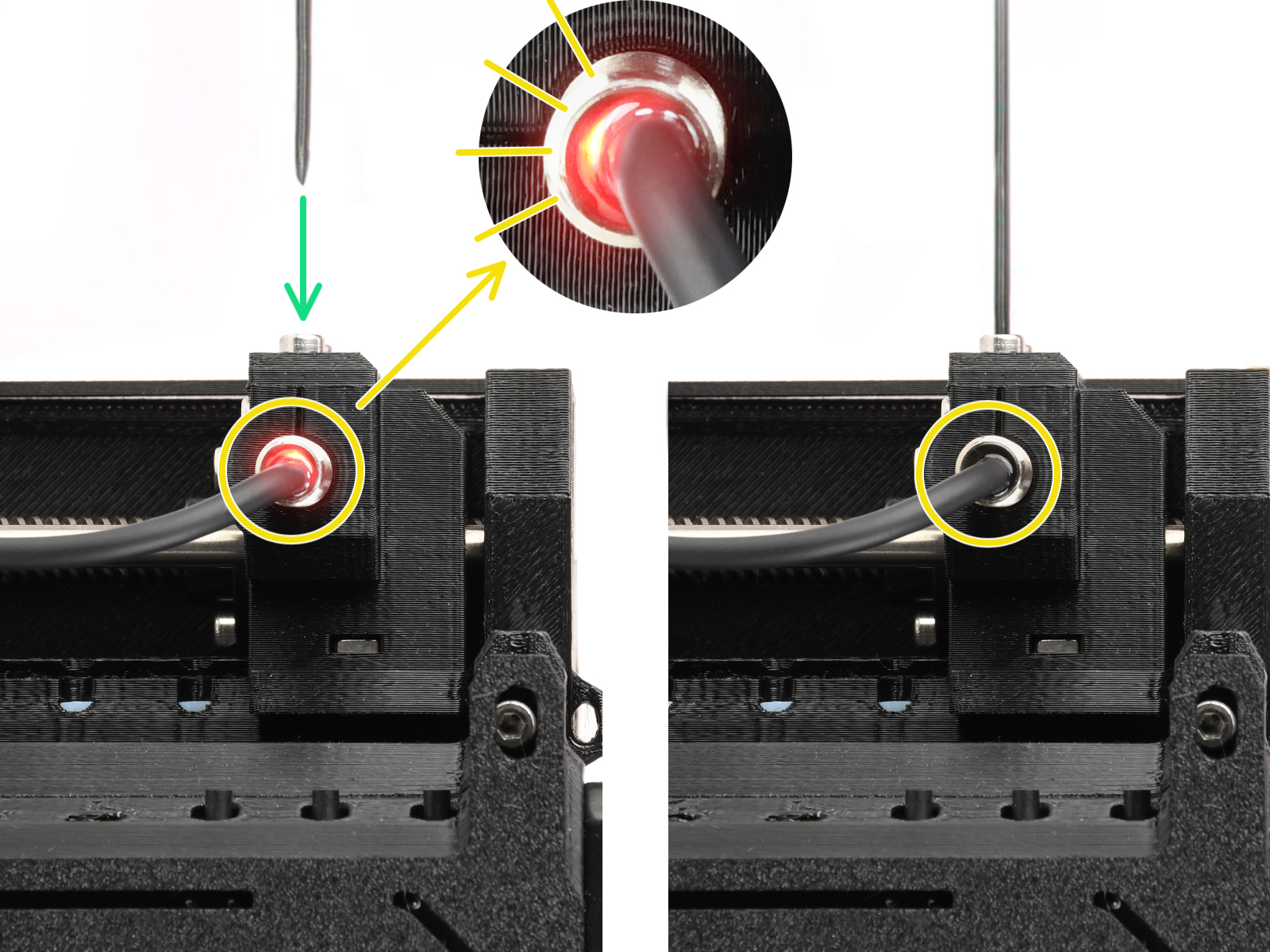
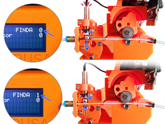
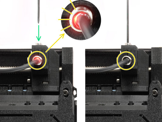
Echa un vistazo a SuperFINDA desde arriba y fíjate en la lucecita roja del interior del sensor que se apaga cuando el filamento levanta la bola de acero de su interior.

Red light = no filament detected = FINDA 0

No light = filament detected = FINDA 1

Si la luz sigue encendida, baja ligeramente la SuperFINDA.

Si la luz no se enciende, levanta la sonda SuperFINDA soltando el tornillo de su lado, moviendo la sonda y volviendo a apretar el tornillo.

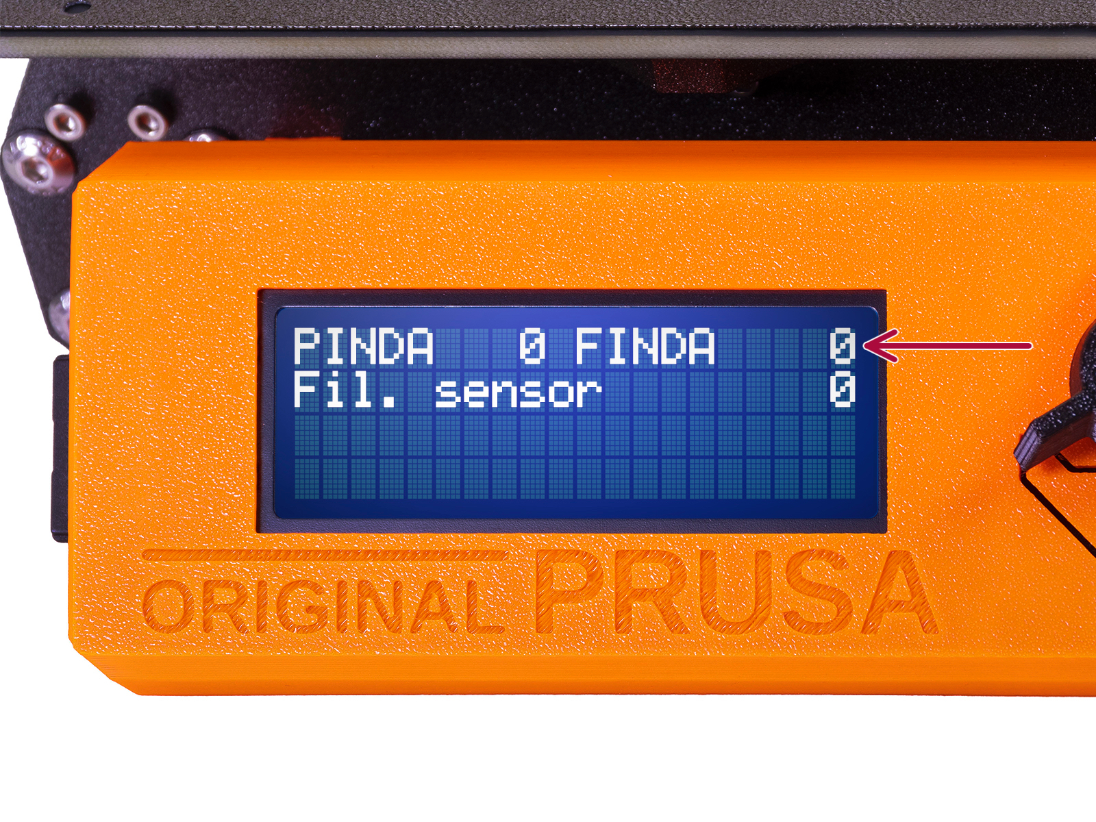
Observa las lecturas del sensor en la pantalla LCD (Menú > Soporte > Info sensor o Info > Info sensor) Ten en cuenta que hay un ligero retraso en las lecturas del sensor en la pantalla LCD; procede lentamente.
Repite la prueba introduciendo y extrayendo el filamento. Observa los valores en la pantalla LCD. Ajuste la altura de la SuperFINDA en consecuencia hasta que obtengas lecturas fiables del sensor cada vez que insertes y retires el filamento.
Error code details (Part 1)

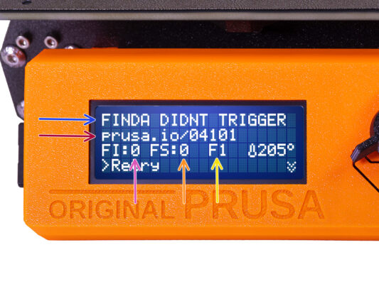
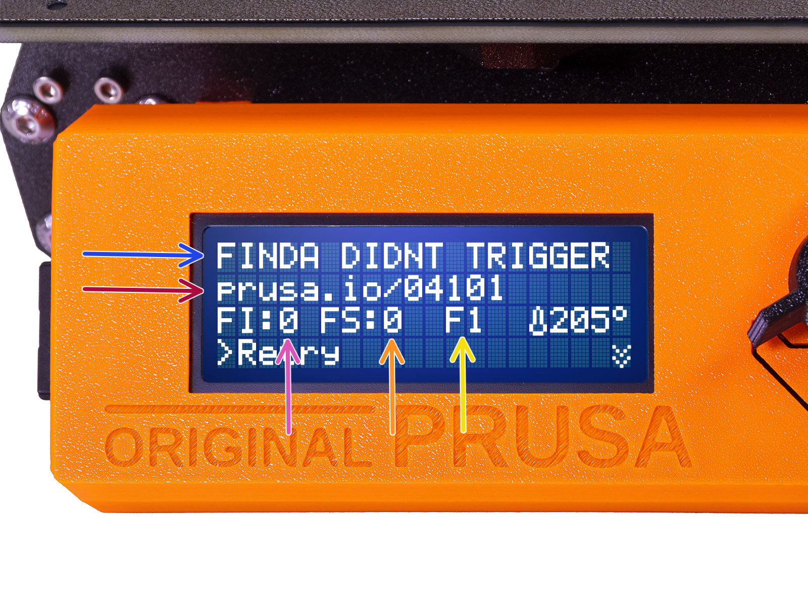
Later on, an MMU error screen will show up if something goes wrong during the operation. See the example image; the first line describes briefly, what's the error about.

prusa.io/04101 is a web address, where you can view a detailed article about the exact issue, and how to fix it.
FI:0 / SuperFINDA sensor reading. FI:0 / OFF = no filament detected. FI:1 / ON = it is detecting a filament.
(Note the FINDA status reading on the LCD has a slight delay.)
FS:0Filament Sensor reading. This is the sensor inside the chimney on the extruder / print head.

F1 is the expected filament position. It means, the selector is in the first position. 1>3 would mean, the selector is changing from the first to the third. F? = position not yet set.
Detalles del código de error (Parte 2)
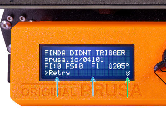
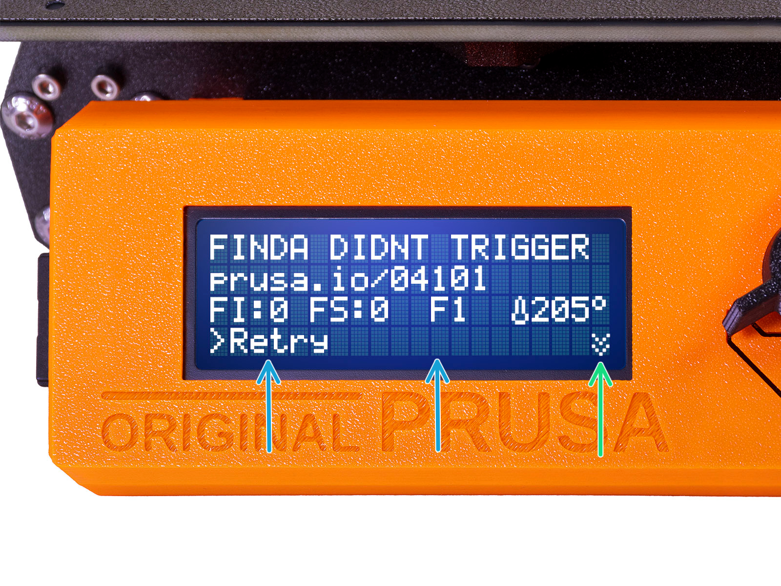
The bottom line are the solution buttons. Some errors have multiple solutions.
In the bottom right corner, selecting the two downward arrows will get you a more detailed error description and possible solution, if the error persists.
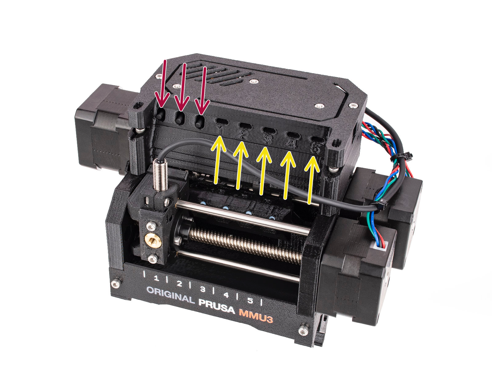
MMU unit being in an error state is also indicated by its LED lights flashing.
While in an ERROR state, the buttons on the MMU unit can be used to resolve the error too.
El botón central suele replicar la función de los botones de solución del LCD.

Note, if the MMU unit is in IDLE state, the buttons have a different functions; For example; If there is no filament loaded, the side buttons can be used to move the selector right and left. But more on that later.
While in an error state, the printer might be beeping. You can change the Sound setting in the Tune or Settings menu.
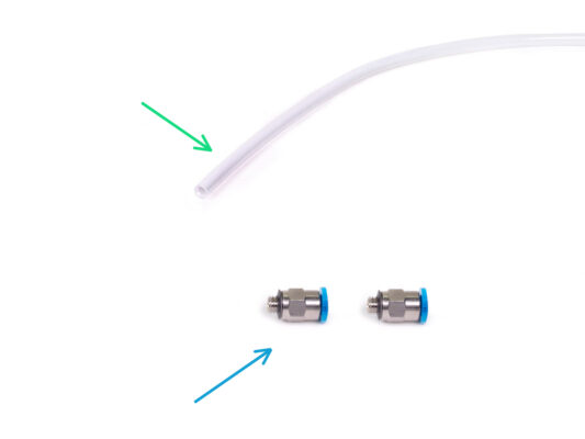
MMU-to-Extruder PTFE tube parts preparation
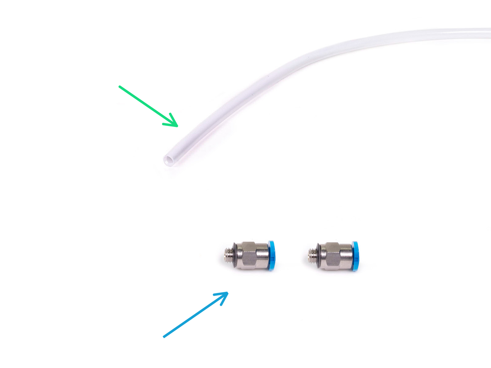
Para los siguientes pasos, por favor prepara:
Tubo PTFE 360x2.5mm (1x)
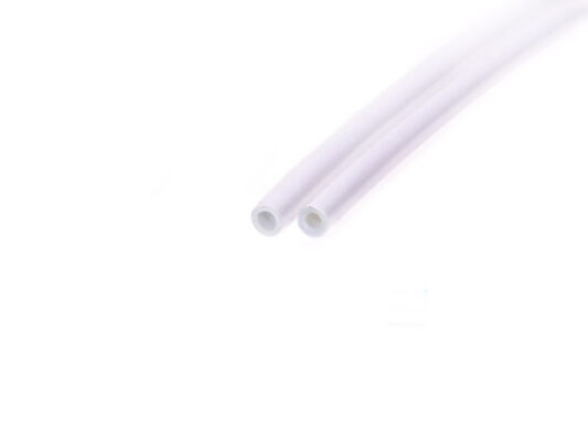
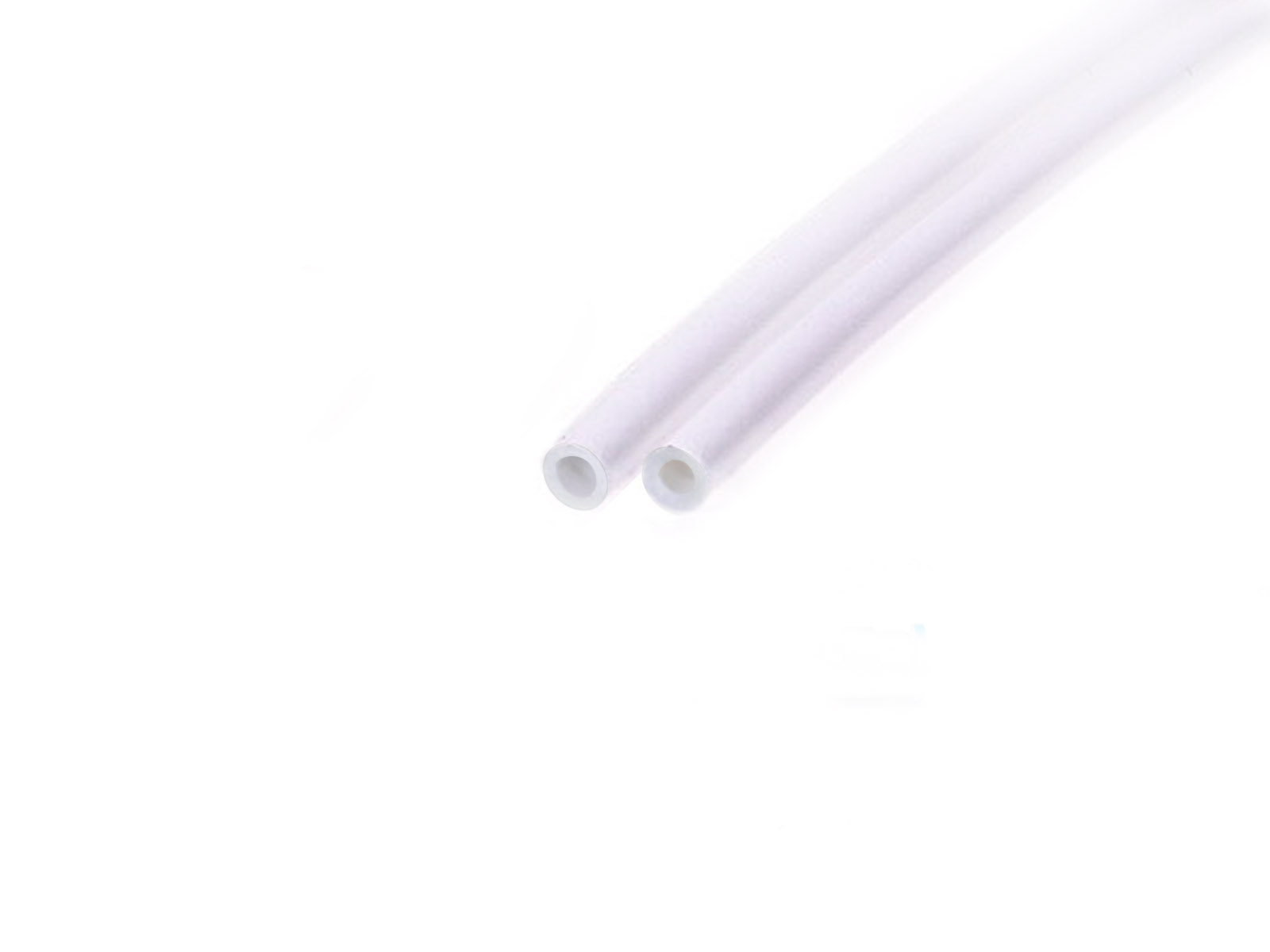
El nuevo tubo de PTFE tiene un diámetro interno de 2.5 mm. En caso de que estés actualizando desde el tubo MMU2S de 2mm de diámetro interno, y tengas problemas para distinguir entre el antiguo y el nuevo, prueba a comparar el diámetro interno de ambos. Mira la segunda imagen. El tubo de la izquierda es el nuevo.
A 2.5mm ID PTFE tube is required for the MMU3.
Racores FESTO (2x)
The fittings may have either a blue or a black collet. Functionally, they are the same.
MMU-to-Extruder PTFE tube
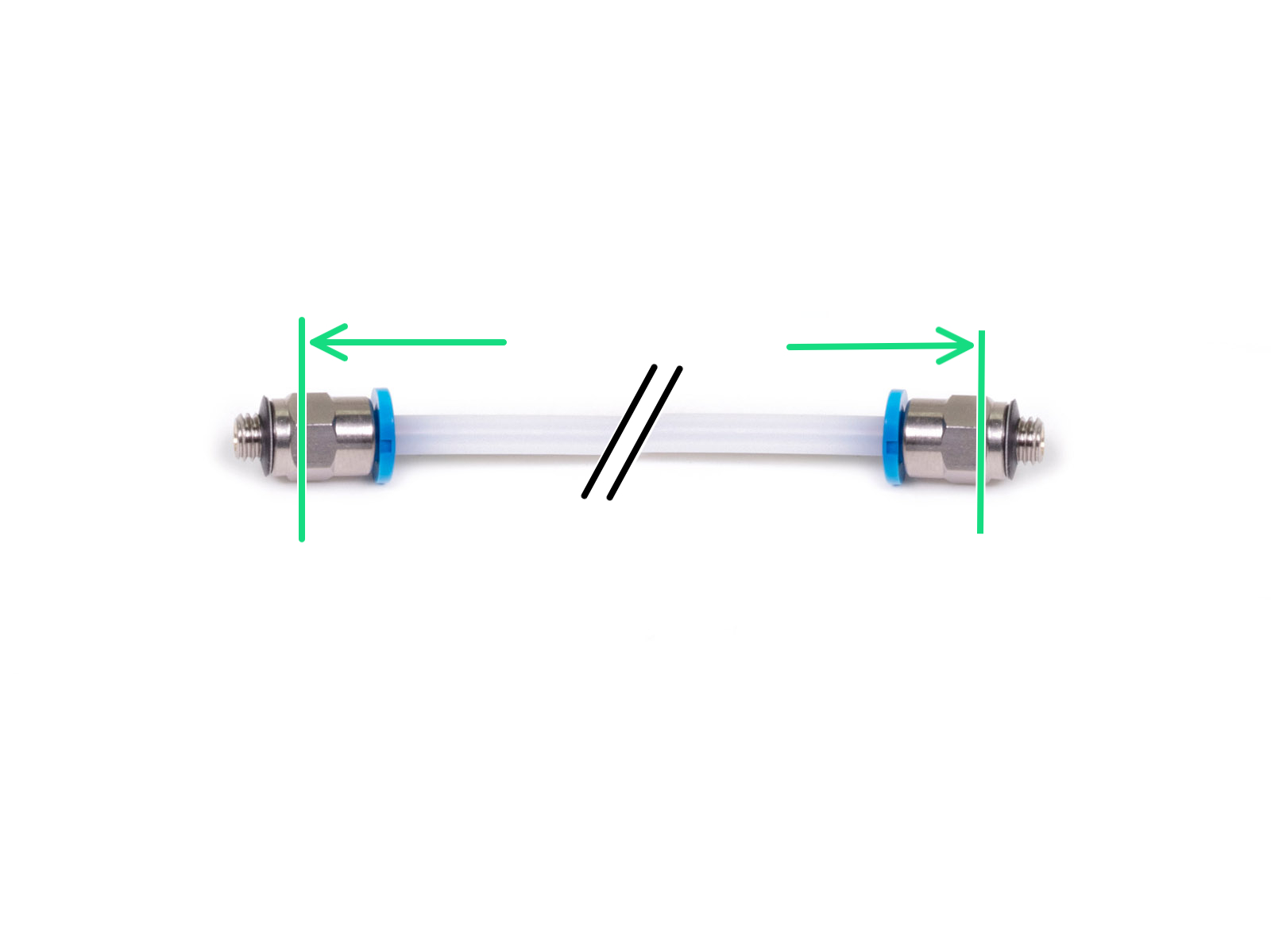
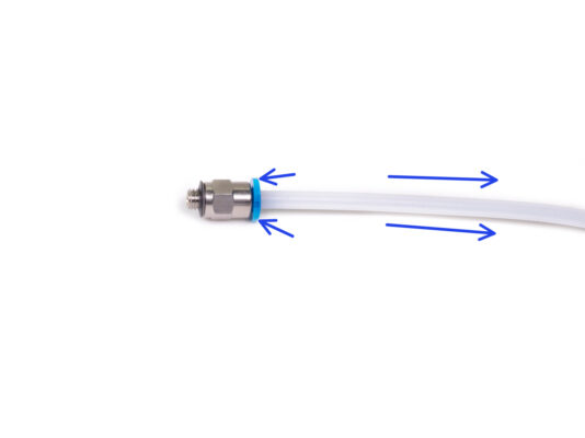
Attach the fittings onto both sides of the new PTFE tube (4x2.5x360mm)
Push the PTFE tube in fully.
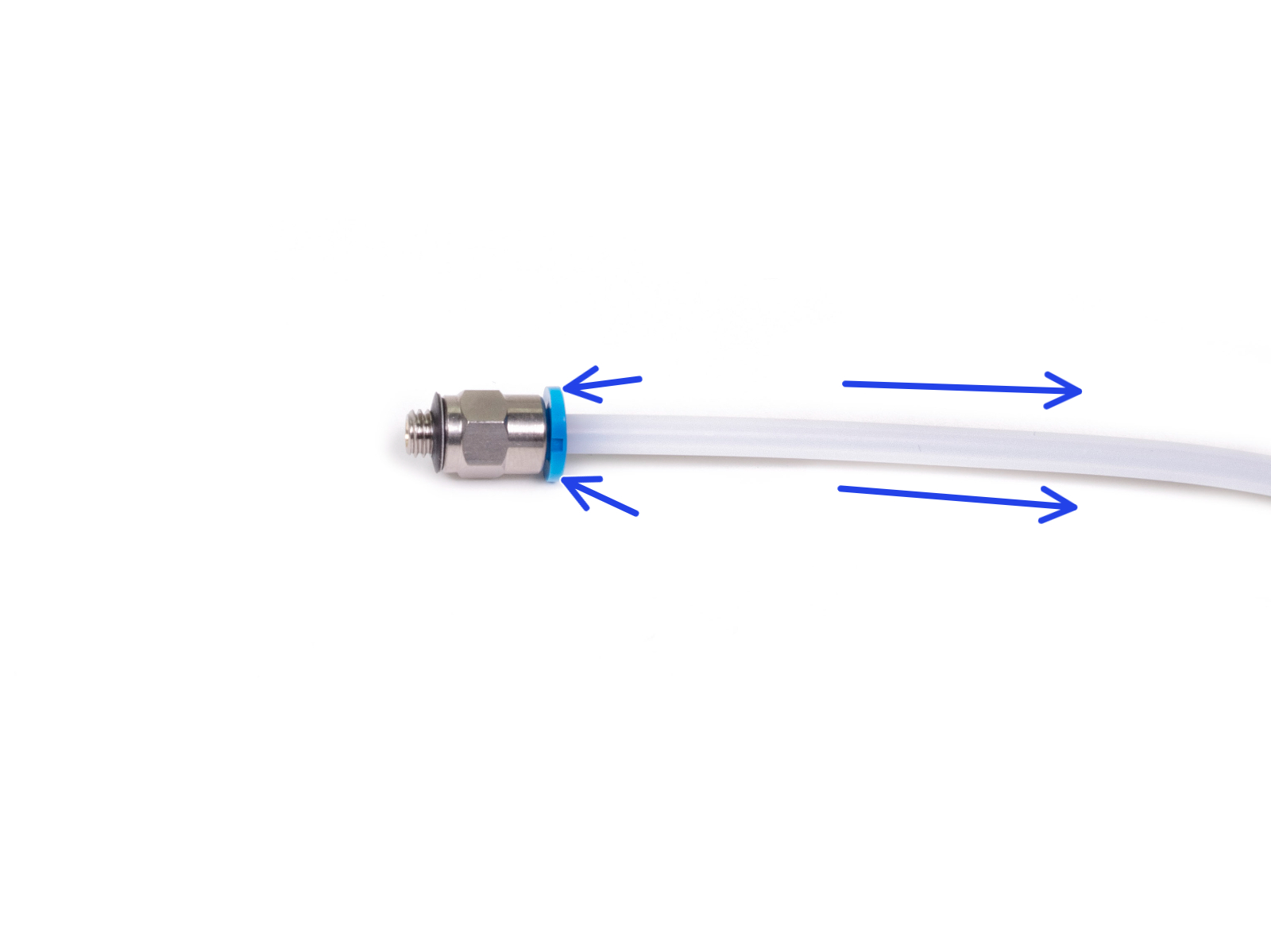
Consejo rápido: Si necesita retirar el tubo de PTFE del racor, presiona la pinza azul hacia dentro. Mientras la pinza está presionada, presiona primero el tubo de PTFE hacia dentro y, a continuación, extráelo por completo.
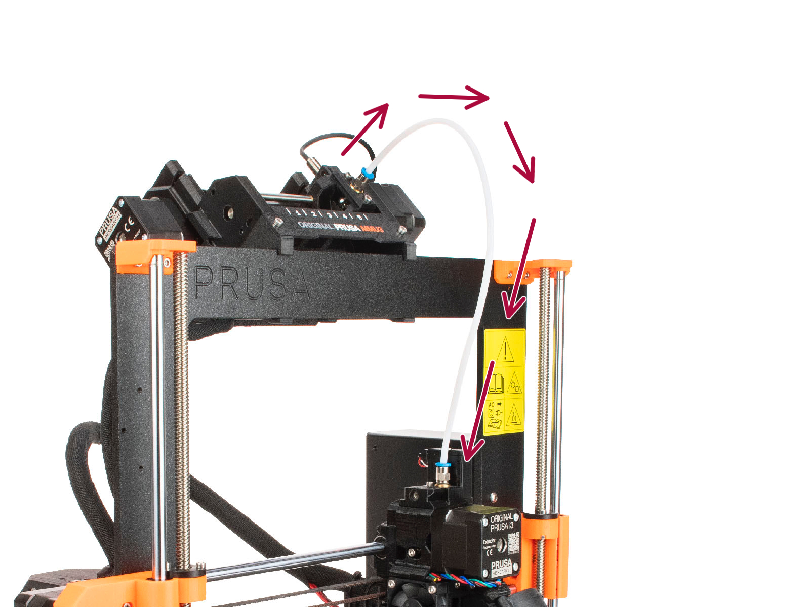
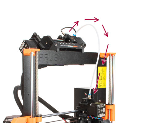
Attach the PTFE tube onto the printer. One end goes onto the selector. The other goes onto the extruder. Tighten the fittings up using the Unikey.
Spoolholders setup
Spoolholders setup
Spoolholders setup

¡Felicidades! La parte más difícil ya ha pasado.

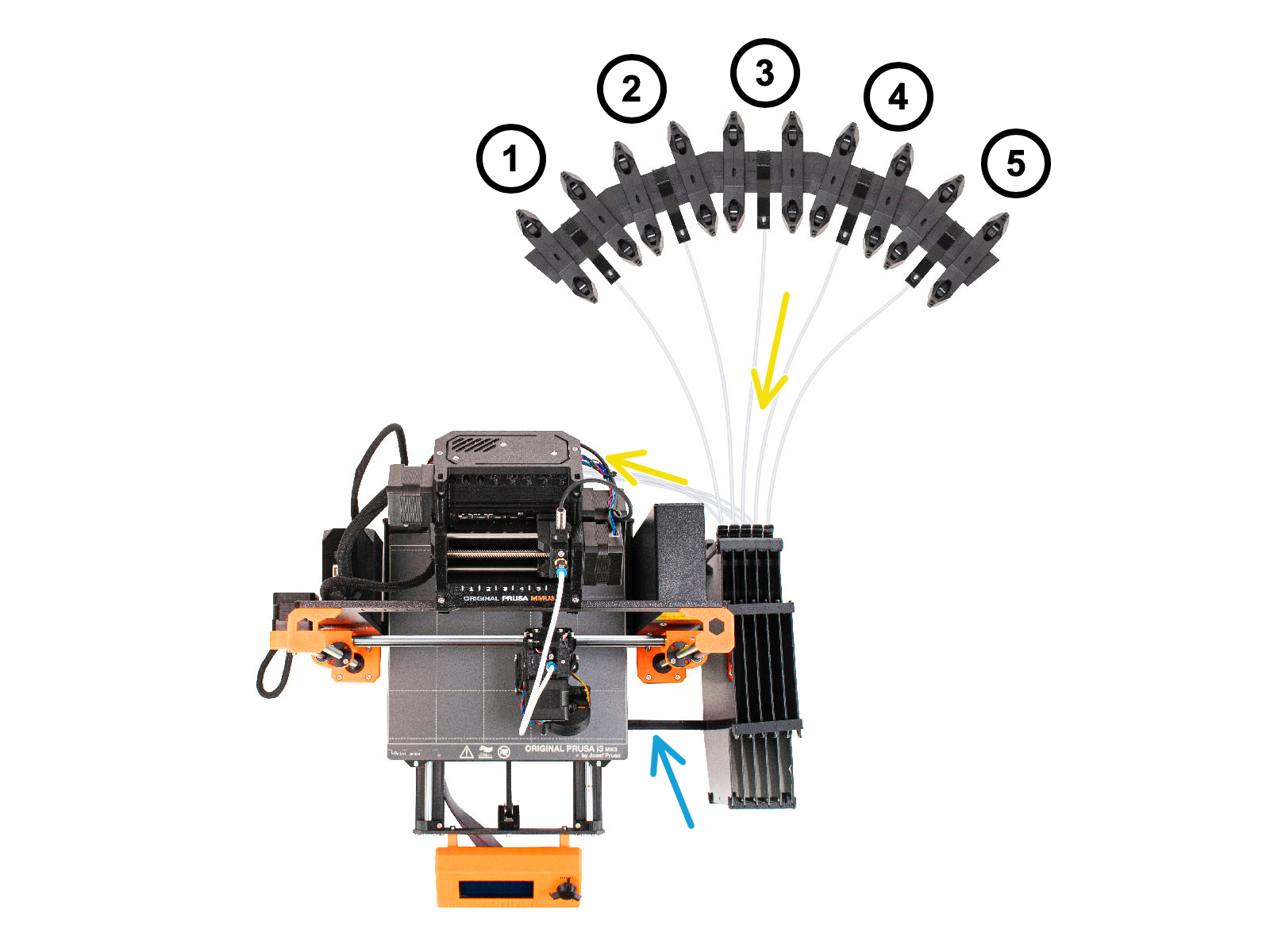
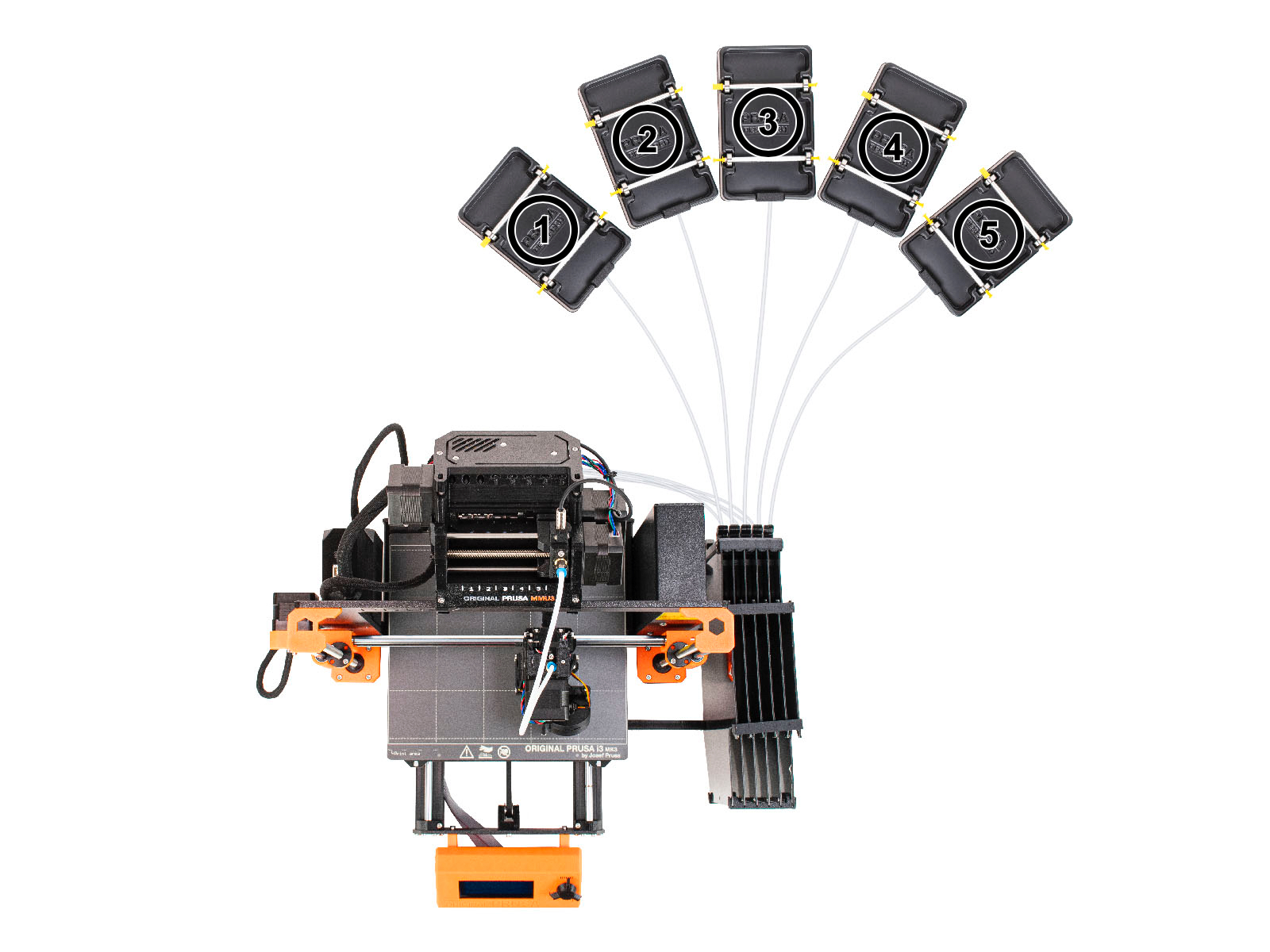
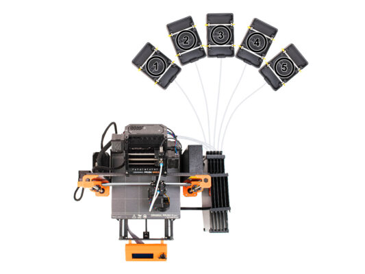
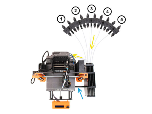
La configuración del buffer y las bobinas de la imagen es la que intentaremos conseguir. Coloca los soportes de bobinas y el buffer como en la imagen.
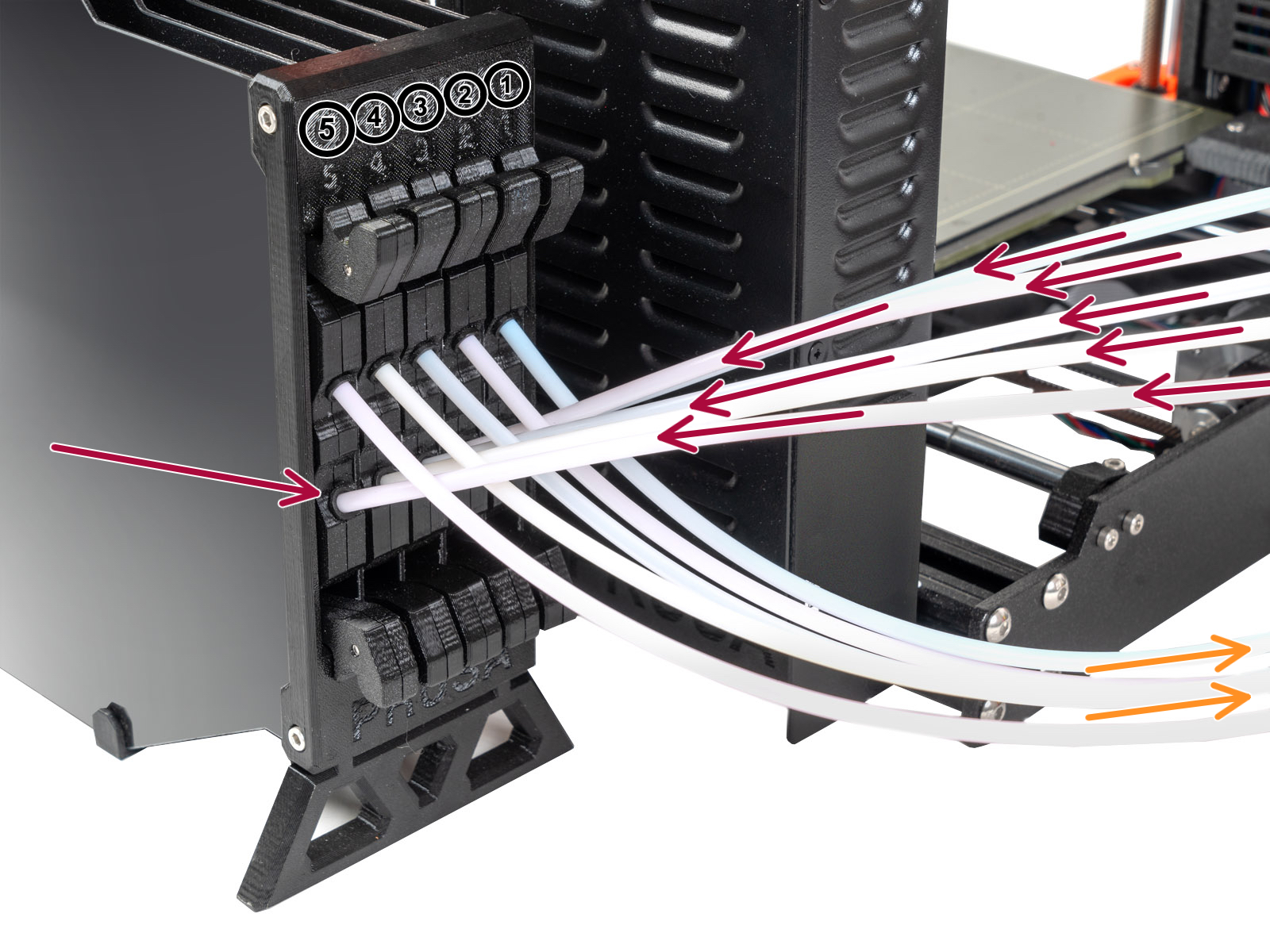
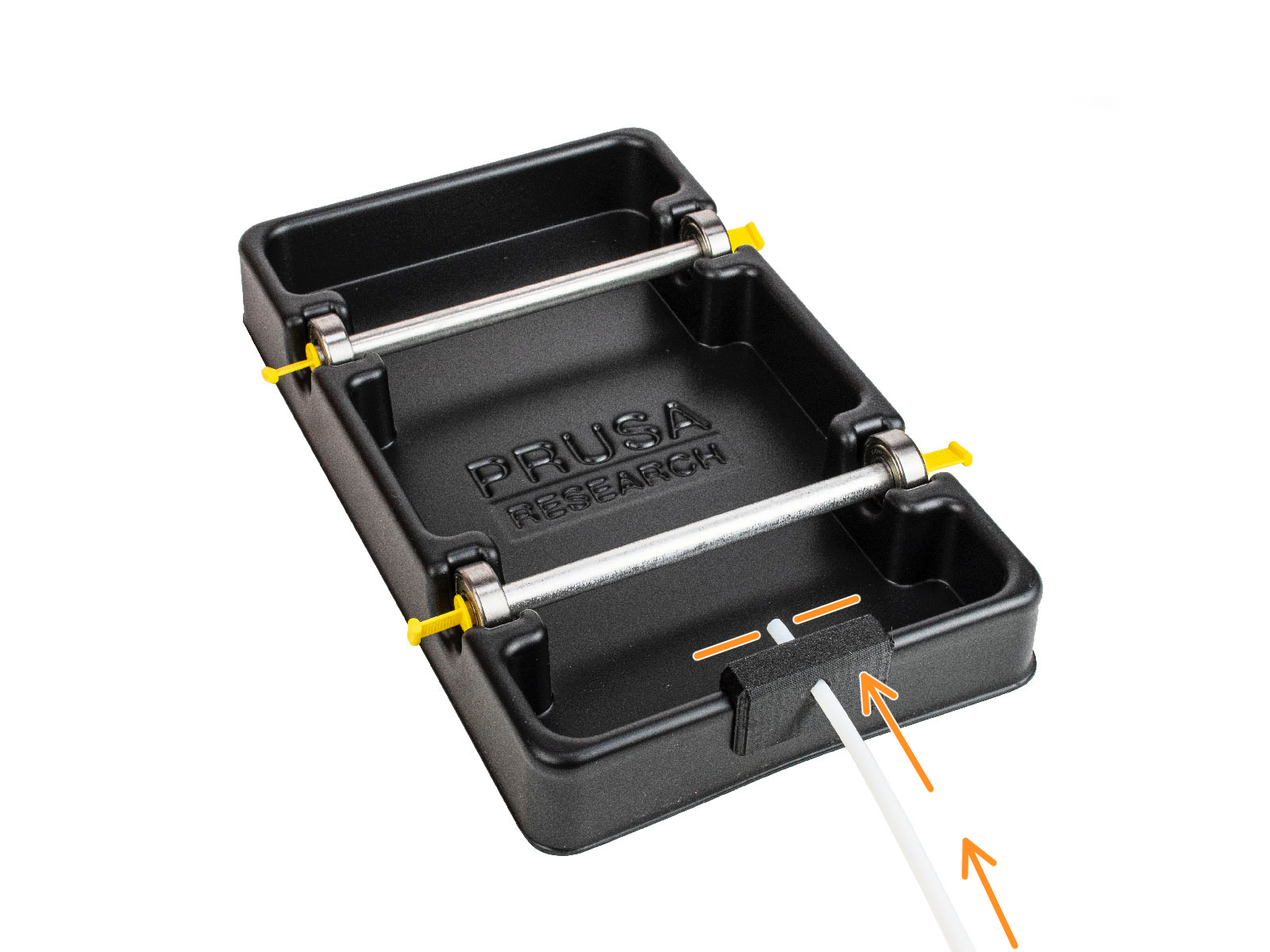
Hook up the "printer holder" part on the buffer to the extrusion on the printer.
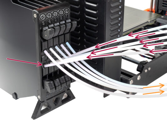
The PTFE tubes go from the spoolholders to the buffer. Then, from the buffer to the back of the MMU.
Observa la posición del portabobinas. Es importante que el filamento tengas un recorrido lo más recto posible y que nada interfiera. Los tubos de PTFE no se deben doblar demasiado. De lo contrario, los filamentos se atascarán.
Note that due to the decreased filament friction in the MMU3 compared to the MMU2S, some of the 3rd-party MMU2S re-winding spool holders might no longer work with the MMU3.
Connecting Buffer PTFE tubes
Connect the PTFE tubes from the MMU unit to the BOTTOM row of collets on the buffer, ensuring you match the numbering on both the buffer and the MMU unit.
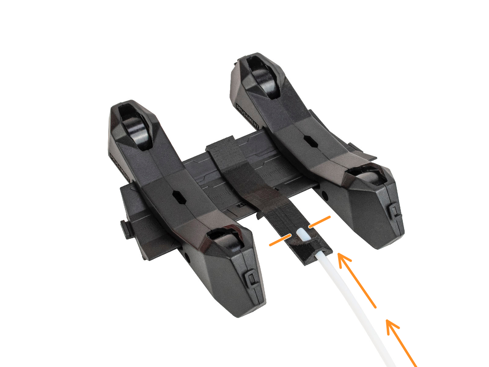
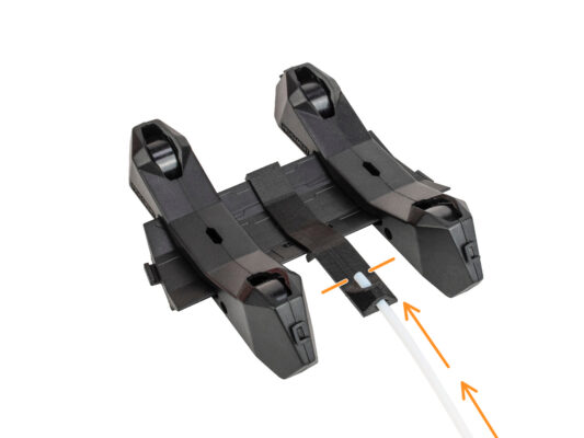
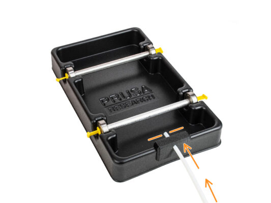
Attach each end of the PTFE tube from the Buffer to the PTFE holder on each Spool holder.
Make sure each spool holder is hooked up to the corresponding filament position number. (marked 1 to 5 on the MMU unit and the buffer.)
¿Fue útil esta guía?

Comentarios

¿Todavía tienes preguntas?

¿Todavía tienes preguntas?

Si tienes alguna pregunta sobre algo que no se ha tratado aquí, comprueba nuestros recursos adicionales.
Y si eso no lo soluciona, puedes enviar una petición a [email protected] o mediante el botón que hay más abajo.
Contacta con nosotros